Quoting wikipedia:
"The Class EF65 (EF65形) is a 6-axle (Bo-Bo-Bo wheel arrangement) DC electric locomotive type operated on passenger and freight services in Japan since 1965.
As of 1 April 2009, JR Freight operated 77 locomotives, JR East operated 8 (EF65-1000), and JR West operated 10 (EF65-1000) locomotives."
I saw this locomotive travelling from Tokyo to the Fuji 5 lakes zones, arriving to Kawaguchiko. This one was pulling a long composition of Taki 43000 tanks.
And this is the Kato model, really well reproduced. I just miss red lights in the back, as it only has white lights in both sides.
Open it pulling up the canopy, use a little screwdriver or toothpicks to help opening as it is clipped to the frame as most prototypes. There is a small plastic piece in the middle of the board that you have also to pull out to then slide the board to one side.
I plan to use a DH05 decoder, from Doehler&Haas, and drill a hole in the case to fit it inside. There is a vent or fan box that can be removed and cut or drill a hole under it to hide the decoder. But you will see with this decoder finally is not needed to cut anything if wires are well placed, not crossing one over another.
I checked the polarity of led to modify the board, not having to remove and turn any of the led if possible. White and yellow wires provide the negative pole, so the negative track going to each led has to be isolated. Positive track will continue providing the positive pole taking current from the rails. This is a common practice when decoders haven't the blue wire (function common wire).
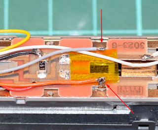
All capacitors must be also removed if they are in the current pick up tracks or can interfere the decoder proper operation. I plan also to keep the led resistor, so I will need to bridge the resistor track and the positive track of one of the led.
You can see here the decoder installed on place. Red arrows show the point where you have to cut the cooper path, and the green arrow points the needed bridge to keep using the single resistor of the board for both led.
Once everything is soldered in place, test the board and lights connecting it directly to the track:
Finally, mount the board again but not bending the motor cooper stips under the board. If you let the strips straight, they pass through the board being isolated from the track current. Solder the motor wires and bend them again but on the top of the board, not under it as it originally is. Isolate with kapton tape near cooper tracks to avoid any short circuit.
Just a test before closing it, and job done!!
Nice locomotive, smooth and reliable. And never looses contact with track and can cross any switch at very slow speeds:
There are many details to add to the locomotive, like handrails, GPS unit, antennas and horns. This is the model finished with all detail parts:


Hi:
ReplyDeleteIn this video
https://www.youtube.com/watch?v=rZl84NXALaM
he says that pin13 is to be connected to pin4, not 2.
?
Hi, that video is not updated. Originally was pin 4, but they moved it to pin 2 in order to allow the connection of an Ethernet Shield. You can check this explanation in the DCC++ website: https://sites.google.com/site/dccppsite/videos/dcc-base-station
Delete"NOTE: There has been an update to the Mega 2560 version of the software posted to GitHub since this video was uploaded. In order to allow for the addition of an Ethernet Shield, the Program Track signal generation has been changed from Pin 4 to Pin 2. This means that with the most recent version of the software you should use a jumper wire to connect Pin 2 to Pin 13 (NOT Pin 4 to Pin 13 as indicated in the video). November 15, 2015"