A new functionality has been released for SVLocoIO firmware. This is the Arduino program we use for all I/O Loconet modules. This means, it is the main Arduino software to manage sensors and outputs (street lights, layout illumination, ...).
It was missing a functionality that other boards do, which is to inform about the state of the inputs (sensors) at power on. When the command station is turned on, or the power on button of your software like Rocrail or iTrain is pressed, the module will send the current state of those ports configured as input.
With a bit more of technical detail, when a OPC_GPON command is sent throuth Loconet, the board responds a OPC_INPUT_REP message for each configured input.
If you want to deactivate this functionality, delete or comment the line in the top of the code:
#define INFORMATPOWERON
I also corrected some errors when calculating the input number of a pin. It was affecting to the debug mode making the input numbers to be printed wrong. With this correction the maximum input number has been increased to 2048.
You can download it from: https://github.com/ClubNCaldes/SVLocoIO
NOTE:
If you use this firmware with GCA185 Loconet shield board, remember you don't need the pulldown resistors of the board as the program uses the Arduino internal pullup resistors.
Showing posts with label Software. Show all posts
Showing posts with label Software. Show all posts
Sunday, September 1, 2019

Sunday, December 4, 2016
PSX DenshaDeGo Loconet controller
In my last trip to Japan I found an old PSX "Densha De Go" Japanese controller. This is a controller simulating a train cab and used with that train simulator game, very popular in Japan.

I don't remember if I found it in a BookOff second hand store or in Mr Potato, Last one is a very famous retro gaming shop in the heart of Akihabara district in Tokyo.
My idea was to use the controller to move trains in my layout, and to accomplish that I would use an Arduino acting as interface between the PSX controller and my Loconet network.
Let's check the hardware needed:
1 x Arduino UNO. (Another Arduino version is also possible)
1 x Loconet shield. As always that you want to interface Arduino and Loconet, you need a Loconet shield. You can build it your own, or buy it directly to the Rocrail guys. The item code is GCA185 and here you have all the information about it and the electrical schemes if you want to build it by your own: http://wiki.rocrail.net/doku.php?id=gca185-en
1 x Sensor Shield v5. This is not strictly needed, but makes it easier to connect wires and build the prototype before soldering everything in place. You can have it from ebay for 2$
You will need also some Dupont female to female jumper wires for easy connecting and testing of the prototype.
Connections:
Plug the Loconet shield GCA185 on top of Arduino UNO, and Sensor shield on top of GCA185. Then you have to connect the pins of the PSX joystic to the following Arduino pins if you want to use directly the Arduino sketch I'm providing later on in this post:
PSX pin 1 (DATA) to Arduino PIN 12
PSX pin 2 (COMMAND) to Arduino PIN 11
PSX pin 4 (GND) to Arduino GND pin
PSX pin 5 (VCC) to Arduino +5V pin
PSX pin 6 (ATT) to Arduino PIN 10
PSX pin 7 (CLOCK) to Arduino PIN 13
You can check in this page all information about PSX controller, also how to identify which is the pin number 1 of the connector: http://www.gamesx.com/controldata/psxcont/psxcont.htm

Here you have an image of my temporary connections of the PSX connector and the Arduino Sensor shield for further clarification:


Software:
Finally, you need to compile and upload the following sketch into the Arduino board:
https://github.com/ClubNCaldes/ArduinoDeGo
To be able to compile the sketch you need to add two libraries to the Arduino environment:
MRRWA Loconet library: http://mrrwa.org/download/
PSX library: http://playground.arduino.cc/Main/PSXLibrary
The first one is the library in charge of Loconet communications. You have many examples included in the library. I used of them, Loconet Throttle, as basis for making the current sketch. The example turns the Arduino in a Loconet Throttle receiving the commands through the serial monitor. You only need to change it a little bit to use any device connected to Arduino. In my case I changed it to use a PSX controller, but you can connect a potentiometer, a LCD display and a keypad or anything you imagine to build your personalized throttle.
The second one is a library written by Kevin Ahrendt and based on the PSX communication protocol analysis from Andrew J McCubbin. I also had to do some reverse engineering as this controller is not like the normal ones. And I found the brake throttle is not working properly, some times it is sending strange values. That's why you will find in the sketch some weird code to skip strange values that my controller sends some times. But if it works with my broken controller, I guess it will also work properly with a good one.

If you have any question just comment under the post or open an issue in the GitHub repository. If it works well and you try it, you can also comment. :P

I don't remember if I found it in a BookOff second hand store or in Mr Potato, Last one is a very famous retro gaming shop in the heart of Akihabara district in Tokyo.
My idea was to use the controller to move trains in my layout, and to accomplish that I would use an Arduino acting as interface between the PSX controller and my Loconet network.
Let's check the hardware needed:
1 x Arduino UNO. (Another Arduino version is also possible)
1 x Loconet shield. As always that you want to interface Arduino and Loconet, you need a Loconet shield. You can build it your own, or buy it directly to the Rocrail guys. The item code is GCA185 and here you have all the information about it and the electrical schemes if you want to build it by your own: http://wiki.rocrail.net/doku.php?id=gca185-en
1 x Sensor Shield v5. This is not strictly needed, but makes it easier to connect wires and build the prototype before soldering everything in place. You can have it from ebay for 2$
You will need also some Dupont female to female jumper wires for easy connecting and testing of the prototype.
Connections:
Plug the Loconet shield GCA185 on top of Arduino UNO, and Sensor shield on top of GCA185. Then you have to connect the pins of the PSX joystic to the following Arduino pins if you want to use directly the Arduino sketch I'm providing later on in this post:
PSX pin 1 (DATA) to Arduino PIN 12
PSX pin 2 (COMMAND) to Arduino PIN 11
PSX pin 4 (GND) to Arduino GND pin
PSX pin 5 (VCC) to Arduino +5V pin
PSX pin 6 (ATT) to Arduino PIN 10
PSX pin 7 (CLOCK) to Arduino PIN 13
You can check in this page all information about PSX controller, also how to identify which is the pin number 1 of the connector: http://www.gamesx.com/controldata/psxcont/psxcont.htm

Here you have an image of my temporary connections of the PSX connector and the Arduino Sensor shield for further clarification:


Software:
Finally, you need to compile and upload the following sketch into the Arduino board:
https://github.com/ClubNCaldes/ArduinoDeGo
To be able to compile the sketch you need to add two libraries to the Arduino environment:
MRRWA Loconet library: http://mrrwa.org/download/
PSX library: http://playground.arduino.cc/Main/PSXLibrary
The first one is the library in charge of Loconet communications. You have many examples included in the library. I used of them, Loconet Throttle, as basis for making the current sketch. The example turns the Arduino in a Loconet Throttle receiving the commands through the serial monitor. You only need to change it a little bit to use any device connected to Arduino. In my case I changed it to use a PSX controller, but you can connect a potentiometer, a LCD display and a keypad or anything you imagine to build your personalized throttle.
The second one is a library written by Kevin Ahrendt and based on the PSX communication protocol analysis from Andrew J McCubbin. I also had to do some reverse engineering as this controller is not like the normal ones. And I found the brake throttle is not working properly, some times it is sending strange values. That's why you will find in the sketch some weird code to skip strange values that my controller sends some times. But if it works with my broken controller, I guess it will also work properly with a good one.

If you have any question just comment under the post or open an issue in the GitHub repository. If it works well and you try it, you can also comment. :P
Sunday, May 29, 2016
New projects and organization of the blog
I'm sorry to have my blog a little bit unattended, but I'm involved in some interesting projects that are taking all my free time.
Complete digital system (Loconet and DCC) based on Arduino
In the Arduino side, my purpose is to build a complete digital system based on this fantastic open source platform. Until now I was using Arduino just to implement some Loconet modules with special functionalities that I was not able to find in the market. Those developments where always thanks to Alex Shepherd and his Loconet libraries for Arduino (www.mrrwa.org). Peter Giling, from Rocrail team, created an interface board usable with MRRWA libraries that enabled those project from the hardware side.
Two months ago I found another interesting development to turn Arduino into a complete DCC command station. It has no possibilities to be connected to an standard bus like Loconet, but it can be connected to JMRI and Rocrail via the USB serial port of Arduino or an Ethernet shield.
Having all the mentioned code, I plan to merge it and have a complete DCC command station with Loconet connection. For that I need some changes to the Loconet Shield (GCA185) from Peter Giling as it should have the Loconet terminator for all system to work properly. It would be also very useful to have a power source of 12Vcc feede from this command station board to the DB9 connectors.
Unexpectedly, a friend from India wrote me and offered his help to develop not only this shield, but a lot more of useful boards to develop this complete digital system (Loconet + DCC) for Arduino. I'll be posting all information here as I get some free time. As always, all my code will be Open Source and public, so everybody can contribute and expand it.
Source code and blog reorganization
I'm also working in a reorganization of the sections of the blog and a common repository for all source code. I'm moving all .ino files to github. I think it's the best option, or at least better than shared spaces with no specific source code support like I'm doing with Google Drive.
New standard for N-scale digital modules
Members of Club N Caldes are quite excited to build our digital system ourselves, and we want to apply it to modules. At least in Spain, is very difficult to see digital modules in train fairs. Until now each member had his own layout, and we were sharing our knowledge and helping ones to the others. As soon as we have all software and hardware ready we want to define a norm to construct our modules and be able to assist to some of the big module fairs.
We plan to use EuroN norm as it is the most extended here, and redefine or add an extension to the norm for digital use. Some requisites are the possibility to change rail current to analogue if desired, keeping the management of switches, lights or any other automatism through Loconet.
New train fair in Logroño (La Rioja - Spain)
Also came to me the opportunity to collaborate in the organization of a train fair in Logroño. I think it will be a very special one, as it will be held in a magnificent place, not the common pavilions. Also this Spanish region is very well known by its wines, and in Autumn the landscape and red colours of the vineyards are superb. We also plan to add an extra value making some workshops and talks for both beginners and seniors in the hobby. But I still have to wait a little bit to post more information. I'll do it soon.
So, the plan is to develop our digital - open source system, make some modules, and assist to the train fair in Logroño in October to present it. We will be quite busy for the next three or four months....
I'll keep you informed!
Sunday, March 6, 2016
Arduino 8 servos module with feedback
I've been always using servos to move my switches. I use GCA136 boards, from Peter Giling, plus GCA137 boards mounted on top to feed the switch frog. A friend asked me if it would be possible to drive servos with Arduino and make a cheap module, and that's what I want to share with you.


This module cannot manage frog polarization, if you need that use Peter Giling boards. But just to move servos, is a great and cheap solution. It's possible to adjust the movement and speed of each of the 8 servos. And the module sends back 8 feedback signals for the software to know when the servo movement has finished and can allow move a train on it. Many servo modules that you can find in the market cannot be used with slow movement because trains are released before reaching the end position and provoques short circuits or derailments.
Configuration is very easy, using the GCA50 configuration screen of Rocrail. It has an special tab for servo adjustment.
So, let's go for the shopping list:
An Arduino UNO:

A Loconet shield GCA185:

And finally a Sensor Shield V5. This is just to make the connection of servos easy:
Sketch is using pins 2,3,4,5,6,9,10 and 11 to connect servos. Pin 13, connected to the on board led, is also reserved and will be activated during a servo movement.
You can download the last version of the sketch (software) for Arduino from the ClubNCaldes github repository:
This sketch is using the ServoTimer2 library. This is a special library developed by Michael Margolis not using the internal Timer1 of Arduino as this timer is already in use by the Loconet libraries and wouldn't work. I had to fix the code to make it work with the last version of the Arduino environment and you can find also this fixed library in the code repository with the sketch.
Once uploaded, you can configure it going to GCA50 configuration screen in Rocrail, under "Programming" menu. In this screen go to Addresses tab and click the Query button. By default sketch is configured with the 81/1 identification, and it should be shown in the screen. It's recommended to change first of all this address to any other number. You can change it in the general tab.
Going to the Easy Setup tab you can read the board configuration clicking the button Get All. The first 8 ports must be configured as output and assign an output number for each of the 8 servos. The last 8 ports, from 9 to 16, are the input numbers assigned to the feedback signal of each servo. You can use the same number for the input as assigned to the output. In Loconet input numbering is independent from the outputs:

Click the Set All button to write configuration into the board. The last tab labelled Servo is used to adjust the movement and speed of each servo:

Select which of the 8 ports (=servos) are you configuring. Each of the two positions have a range from 1 (equivalent to 0 degrees) to 127 (equivalent to 180 degrees). "V" is the speed of movement, being 0 the slowest and 5 the fastest. Each time you press the Set button configuration will be stored and servo will move one side and the other at the selected speed.
Current to feed arduino and servos is taken directly from Loconet, but you can feed also the sensor shield with an external 5V power supply removing the jumper in the sensor shield board.
Here you can see it in action. I hope you like it:
Monday, February 22, 2016
Build your own DCC Command Station for 8$
I want to share here the information from DCC++ (https://sites.google.com/site/dccppsite/home) to build a DCC command station using Arduino. It is a complete DCC command station, supporting the full set of NMRA Digital Command and Control (DCC) standards, including:
But the best thing is that it will only cost you 8$ using the basic Arduino UNO, or 12$ using a more powerful Arduino MEGA. Yes, just 8$!!!! I suggest you to use Arduino MEGA in view of future expansions I want to implement, like a Loconet bus or the possibility to work in digital and analog mode. Don't be afraid about the difficulty to mount the system, you DON'T NEED to solder anything, just plug, upload the program, and run!!!
To mount this command station you need the following hardware:
Arduino MEGA: It can be found in ebay for 8$, I bought it here. Arduino UNO is also suitable, but I prefer a MEGA board as it is faster and more expandable.

Arduino Motor Shield R3: It will not cost you more that 5$ in ebay, here is where I bought mine.

And the following is the needed software to make it run and manage and program trains:
Arduino IDE: This software is used to program Arduino or upload any already made software/firmware (or sketch in Arduino language) to the board. It will be used only once to upload the DCC++ command station sketch to the Arduino board, or in the future to upload a new program version with more features. It can be freely downloaded from Arduino official page: https://www.arduino.cc/en/Main/Software
Base Station DCC++: This is the software or firmware/sketch we will upload into Arduino board using the previous Arduino IDE. Just download and extract it in any folder in your computer. It can be downloaded from DCC++ page or directly clicking here.
JMRI: This is the program that "talks" to the command station and allows you to drive trains, move switches, program decoders, ... I plan to change the DCC++ command station protocol to make it more standard and be able to use also other software like Rocrail, but for now it must be used with JMRI. Download this software from http://jmri.sourceforge.net/download/index.shtml and install it. Under "Production Release" section of this page there are JMRI versions for Windows, Linux and Mac OS. This is a very good software, and freeware, and many times I use it to program decoders better than other software.

Now you can plug the motor shield board on top of Arduino. There is only one position how the motor shield fits on top, and pins are numbered in both boards, so just make sure pin 0 of the motor shield is connected to pin 0 of Arduino board.
I you are using an Arduino UNO, you have to bridge pin 10 and 12 in the motor shield (blue wire in the following photo), and pins 5 and 13 (red wire):


Connect your 12Vcc power source to the screw terminals of the motor shield. Positive is connected to the screw terminal "VIN", and ground to "GND".
In the same screw terminal block, "A+" and "A-" are connected to your main track, and "B+" and "B-" to the programming track.
Connect Arduino to the PC with a USB cable. Probably your Arduino already came with it. Your PC should recognize then a new serial port.
Now we will upload the firmware (or sketch in Arduino terms) to the board. Go to the folder where you extracted the Base Station DCC++. Inside the "DCCpp_Uno" folder double click the file named "DCCpp_Uno.ino".

This will automatically open the Arduino IDE. You have to set up your connected Arduino board under "Tools" menu, option "Board". And also select the serial port as your computer detected Arduino when connected. This is also under "Tools" menu, option "Port":

Now everything is ready to upload the program, and to archive that you only need to click the upload button on the top left corner. After some second you should receive a message saying "Program uploaded" if everything went ok:

To set up JMRI to work with your brand new command station, just follow these instructions: http://jmri.sourceforge.net/help/en/html/hardware/dccpp/index.shtml
And you are ready to test your system. First of all, go to "Power Control" option inside "Actions" menú. Click the power on button of the new opened window, and led on the motor shield should light on if everything is correct. Now you can open a throttle, put a locomotive on the track, select its address, and push the throttle up!!! There is also a very good utility in JMRI to monitor the power drained by the track:

Now also Rocrail is compatible with this command station, and allows to use the other pins as input or outputs with the standard sketch from DCC++. You can use a connector to allow up to 4 GCA boards to be connected to the command station:
 And you can configure pins as input or output as needed:
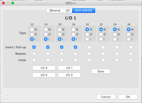
Even more, Rocrail has a special slot management with passive slot purge after 30 seconds idle and speed zero and it is compatible also with the Ethernet connection of DCC++ command station.
You can read all the information regarding the use of DCC++ command station with Rocrail here:
Enjoy it, now you have the best price/quality relation command station!!!!
- 2-byte and 4-byte locomotive addressing
- 128-step speed throttling
- Activate/de-activate all accessory function addresses 0-2048
- Programming on the Main Operations Track
- write configuration variable bytes
- set/clear specific configuration variable bits
- Simultaneous control of multiple locomotives
- Control of all cab functions F0-F28
- Programming on the Programming Track
- write configuration variable bytes
- set/clear specific configuration variable bits
- read configuration variable bytes
But the best thing is that it will only cost you 8$ using the basic Arduino UNO, or 12$ using a more powerful Arduino MEGA. Yes, just 8$!!!! I suggest you to use Arduino MEGA in view of future expansions I want to implement, like a Loconet bus or the possibility to work in digital and analog mode. Don't be afraid about the difficulty to mount the system, you DON'T NEED to solder anything, just plug, upload the program, and run!!!
HARDWARE
To mount this command station you need the following hardware:
Arduino MEGA: It can be found in ebay for 8$, I bought it here. Arduino UNO is also suitable, but I prefer a MEGA board as it is faster and more expandable.

Arduino Motor Shield R3: It will not cost you more that 5$ in ebay, here is where I bought mine.
12 Vcc power supply: I use a power source from an old computer (yellow and black wires provide 12Vcc), but any power source with at least 2Amp can be used. For H0 scale, is better a 15Vcc power source, but for N scale 12Vcc is enough.
SOFTWARE
And the following is the needed software to make it run and manage and program trains:
Arduino IDE: This software is used to program Arduino or upload any already made software/firmware (or sketch in Arduino language) to the board. It will be used only once to upload the DCC++ command station sketch to the Arduino board, or in the future to upload a new program version with more features. It can be freely downloaded from Arduino official page: https://www.arduino.cc/en/Main/Software
Base Station DCC++: This is the software or firmware/sketch we will upload into Arduino board using the previous Arduino IDE. Just download and extract it in any folder in your computer. It can be downloaded from DCC++ page or directly clicking here.
JMRI: This is the program that "talks" to the command station and allows you to drive trains, move switches, program decoders, ... I plan to change the DCC++ command station protocol to make it more standard and be able to use also other software like Rocrail, but for now it must be used with JMRI. Download this software from http://jmri.sourceforge.net/download/index.shtml and install it. Under "Production Release" section of this page there are JMRI versions for Windows, Linux and Mac OS. This is a very good software, and freeware, and many times I use it to program decoders better than other software.
HOW TO MOUNT IT
Before mounting the Motor Shield r3 on top of Arduino, you have to cut the pad labeled "Vin" in the bottom of the board. This is to isolate the power input of the shield from the 12V power source that Arduino is also providing:
Now you can plug the motor shield board on top of Arduino. There is only one position how the motor shield fits on top, and pins are numbered in both boards, so just make sure pin 0 of the motor shield is connected to pin 0 of Arduino board.
I you are using an Arduino UNO, you have to bridge pin 10 and 12 in the motor shield (blue wire in the following photo), and pins 5 and 13 (red wire):

In case of Arduino MEGA, only one bridge is needed between pin 2 and pin 13:

Connect your 12Vcc power source to the screw terminals of the motor shield. Positive is connected to the screw terminal "VIN", and ground to "GND".
In the same screw terminal block, "A+" and "A-" are connected to your main track, and "B+" and "B-" to the programming track.
Connect Arduino to the PC with a USB cable. Probably your Arduino already came with it. Your PC should recognize then a new serial port.
Now we will upload the firmware (or sketch in Arduino terms) to the board. Go to the folder where you extracted the Base Station DCC++. Inside the "DCCpp_Uno" folder double click the file named "DCCpp_Uno.ino".

This will automatically open the Arduino IDE. You have to set up your connected Arduino board under "Tools" menu, option "Board". And also select the serial port as your computer detected Arduino when connected. This is also under "Tools" menu, option "Port":

Now everything is ready to upload the program, and to archive that you only need to click the upload button on the top left corner. After some second you should receive a message saying "Program uploaded" if everything went ok:

HOW TO USE IT
To set up JMRI to work with your brand new command station, just follow these instructions: http://jmri.sourceforge.net/help/en/html/hardware/dccpp/index.shtml
And you are ready to test your system. First of all, go to "Power Control" option inside "Actions" menú. Click the power on button of the new opened window, and led on the motor shield should light on if everything is correct. Now you can open a throttle, put a locomotive on the track, select its address, and push the throttle up!!! There is also a very good utility in JMRI to monitor the power drained by the track:

Now also Rocrail is compatible with this command station, and allows to use the other pins as input or outputs with the standard sketch from DCC++. You can use a connector to allow up to 4 GCA boards to be connected to the command station:
Even more, Rocrail has a special slot management with passive slot purge after 30 seconds idle and speed zero and it is compatible also with the Ethernet connection of DCC++ command station.
You can read all the information regarding the use of DCC++ command station with Rocrail here:
Enjoy it, now you have the best price/quality relation command station!!!!
Thursday, January 14, 2016
Layout illumination and weather simulation system

Last year, updating my Rocrail installation, I realized there was a new option in the Tables menu called "Weather" and seemed to be exactly the functionality I was looking for. So, I took a look to the documentation in the Rocrail wiki: http://wiki.rocrail.net/doku.php?id=weather-en
As you can read this functionality to manage ambient lights is compatible with some special systems like RocNet or OpenDCC Bidib, but also with some commercial system, what I liked the most. First of all I took a look to the Philips HUE system:
Philips HUE

Philips HUE consist in a a group of lights connected by wi-fi to some kind of router or concentrator that you can manage to set the intensity and color of each light individually. It's a very good solution because if you are not using Rocrail you can still manage the lighting system with the Philips application. But the bad news are the price of the lamps, too expensive in my opinion and restricted to Philips lamp models.
DMX lights
Next compatible system is called DMX. I made further investigations and learned it is the most standard protocol for managing lighting systems like those used in theaters, concerts and discos. According wikipedia: "DMX512 (Digital Multiplex) is a standard for digital communication networks that are commonly used to control stage lighting and effects."
There is a huge range of spot lights, flood lamps, lasers, stroboscopic lamps, motorized led beamers, ..... but of course we are talking about professional systems, what means each light is expensive because it implements an special DMX connector and protocol to receive the orders.
There is a huge range of spot lights, flood lamps, lasers, stroboscopic lamps, motorized led beamers, ..... but of course we are talking about professional systems, what means each light is expensive because it implements an special DMX connector and protocol to receive the orders.

Lamps can be found in ebay at a moderate price, but you also need a PC interface to convert the orders sent by the software normally through the serial port USB to the DMX format.

Rocrail is compatible with EuroLite USB-DMX512 Pro converter or DMX4ALL, but you have to order them to Germany and cost 80$ or more. Looks like those interfaces are not sold internationally.
At this point, being the DMX-USB interface the difficult issue, I thought about implementing it myself using an Arduino. And I found DMX shields and libraries, but most of them discontinued or even more expensive than a commercial and complete interface. So my hope went out in smoke again.


Art-Net receiver
Last chance, Rocrail is also compatible with an Art-Net node receiver. This is a lighting control protocol which appeared after DMX512 to allow connections through LAN or wi-fi networks to DMX systems. Basically it is an encapsulation or transport protocol for DMX based on UDP though a normal computer network. You can read more about it in wikipedia.

This system has more or less the same problems than the previous one. You need an Art-Net receiver, receiving UDP commands (that's the easy part), but again you have to transform this commands to DMX format. If you want to do it yourself with an Arduino, you need a DMX shield and use DMX lights.
Final solution
Art-Net looks like a good protocol. You can access the lights from the wired lan or via wi-fi, and you don't need a special interface connected to PC. There are also free applications for PC, tablet or smartphone to manage Art-Net lighting systems. And I found these libraries from Christoph Guillermet (karistouf) for Arduino implementing an Art-Net receiver using a cheap 5$ Ethernet shield: https://vvvv.org/contribution/artnet-arduino-set-v3.1-0
Inside the libraries it gives the idea of using the PWM outputs to manage RGB lights or leds according to the Art-Net commands received, so you can skip all the DMX stuff, and I found this idea perfect and started to assemble my lighting kit:
 |
| Arduino UNO |
 |
| Ethernet Shield |
 |
| Sensor Shield V5 |
 |
| 4 MOSFET breakout board |
 |
| 12V Pure white led strip |
 |
| 12V RGB led strip (not addressable) |
First of all plug the ethernet shield on top of Arduino UNO, and Sensor shield V.5 on top of the Ethernet. Sensor shield provides and easy way of connecting sensors and breakout boards (like the mosfets boards) to Arduino using cheap Dupont cables that you can also buy in ebay.
Using Dupont wires (female in both ends) connect outputs 3,5,6 and 9 to the Mosfet board. These Arduino outputs are PWM (you can adjust the intensity), and will correspond to channels 1,2,3 and 4 of the ArtNet receiver.
Connect the pure white led strip to one of the mosfets, and red, green and blue channels of the RGB led strip to the other three mosfets through the screw headers. Feed the power of the mosfets board with 12Vcc power source. I use a normal power source from an old computer.
You can download directly my program for the Arduino HERE. It is based on Christoph Guillermet example. By default uses the IP 192.168.0.30, you can change it in the header of the sketch.
Software configuration
If you are not using Rocrail, I suggest you to change and start using it. :P
Well, if you still want to use your system, for sure it will not have a weather functionality and an Art-Net implementation. So you can use any freeware Art-Net console in your PC or tablet to adjust your new illumination system.
If using Rocrail, the best way is to download the weather example plan because the documentation is not completely clear and easy to understand. These are the basic steps to make it work:
First, define a new command station of type "dmxartnet" in Rocrail Server configuration and setup the IP assigned to your Arduino in the sketch:

Then you need to create an output object of type "light". In the "Interface ID" select this new command station dedicated to lighting. Is important to fill the field Value with 255 and the type of output "Lights":

In the color tab specify the channel of each of the colors and white and the desired color you want when activating the output:

There is an aid to select the color, it's not needed to work just with RGB values:

At this point, pressing the output symbol your led strips should glow in the predefined color. You can create many of them for different ambient lights or an output with strong white to have a good illumination to work on the layout.
But the best thing of all this is to be able to define all the color and intensity sequence depending on the time of your layout clock. This is defined in the Weather section inside the Tables menus:

The basic thing you need here is to define the output (or outputs separated by comma) of your output-light objects to use. In my case I have only one light composed of 4 channels (red,green,blue and white). But you can put some of them ordered from east to west and the software will make light transitions simulating the sun movement. It's possible also to specify different lights for night simulation.
You have different options to make it work. The basic one is to define the time and color for the sunrise, noon and sunset and Rocrail will be calculating the transition according to the time and adjusting your led strip lights. But I prefer to use the color table where you can adjust the exact light during a whole day at 30 minutes steps.

Your lights will be adjusted according to the Rocrail clock. If you set up the clock to run faster, lights will also be adjusted at its rhythm. Finally, you can create several Weathers (one for each season, as an example) and an Action to activate or deactivate each of the defined Weathers. Putting outputs linked to this actions, your lighting system will simulate it.
Last but not least, you can create Themes. I use them to define storms, and can be linked to actions and outputs or any layout event to activate them.

My storm Theme uses another light-output object, but linked to the same white channel of my Arduino Art-net receiver. For the thunder sound, I activate the output linked to a storm sound stored in my "Arduino sound and outputs module" that you can also mount following the instructions of this post.
Here you can see a video example of a sunrise and a storm. Mobile phones do not get properly the real light and color, it's much better that what you can see in the videos, sorry for the poor quality:
Here you can see a video example of a sunrise and a storm. Mobile phones do not get properly the real light and color, it's much better that what you can see in the videos, sorry for the poor quality:
In following post I will try to install RGB Led Flood lamps instead of RGB led strips and several of them to test the sun movement simulation. I will keep you informed!
Wednesday, August 26, 2015
Great advances in Arduino and Loconet !!!
I'm excited to be finally writing this post! I've been for a long time working to find a way to connect Arduino to Loconet network and be able to develop my own modules to create special automations in the layout. Now this is a reality and with great examples.
If you read the first posts about this, I started using a GCA50 board (from Giling Applications) with just the minimum components needed to act as a Loconet interface for Arduino. I was using on that time the first version of the MRRWA libraries for Arduino. Thanks to the examples included in that library programming your own module and interacting with all the components of the layout is a mere child's play. Beginning of this year a new update for the Loconet libraries was released, and now the MRRWA libraries come with even more examples.
Peter Giling took this idea of creating a Loconet shield and developed a prototype board that I tested, and from two months ago the professional boards are available. Its official name is GCA185:

In my opinion this shield and the use of an Arduino is not to replace neither the basic sensor modules nor the outputs module to manage switches (coil or servo motors). The current boards from Peter Giling for those tasks (GCA50, GCA93, GCA77, GCA136, GCA137) work perfect, are smaller, specialized in the function they develop, and not more expensive than trying to reinvent the wheel with an Arduino.
But once you cover the basic needs of a digital layout which are detecting trains and changing switches and you want to go to a "show level" and add sounds to stations and factories, manage the illumination of the layout independently from the PC software, create ambient light and storms, or whatever automation you think, an Arduino with this Loconet shield is able to do all the above and more.
Connecting your Arduino to the Loconet network, it will receive in real time the information of what is happening in the entire layout: detections from the sensors, loco functions, all instructions sent from the command station, software or throttles... But even more, it will be able also to "talk" and not just "listen" to the other components of the layout, including moving or stopping trains, changing switches, activating lights or locomotive functions... And if you add the capabilities of Arduino to use an infinite catalogue of sensors (temperature, infrared, RFID, proximity,...) and devices (wifi, bluetooth, speech engines, mp3 players, displays, keyboards,...) the possibilities of what you can do in your layout grow in an exponential way.
If that's not yet enough, the shield includes two MOLEX connectors to make use of all "interface boards" developed by Peter Giling with the perfect hardware to detect train consumptions, reed sensors, wheel counters, relays,...
And the last but maybe the most useful feature of the shield is the possibility to feed the current for Arduino from the Loconet conectors, and you have both type of them: the standard RJ12 used by Uhlenbrock or Digitrax, and DB9. That last used by Giling boards and much more reliable and with an extra power line of 12V and 3Amp if you use a Loconet booster like GCA101. The shield also has a voltage regulator and can feed all the shields through its own voltage regulator.

I finished this week a stable version of a software for Arduino and the Loconet shield that turns it into a Sound Module (able to play stereo MP3 files assigned to standard output directions each one) plus 16 outputs for illumination or other devices. In the PWM pins is possible to adjust also the intensity and fade effect. And all is configured via LNCV mechanism like any other Uhlenbrock module, so you can configure it from the Intellibox command station or Rocrail software without requiring to upload a new program in the board or access fiscally to the module.
In next posts I'll be sharing my finished Arduino programs and ongoing projects, which include crazy things like using a Densha-de-Go! Playstation controller to drive trains in a digital layout, or manage ambient lights to create weather conditions.

If you read the first posts about this, I started using a GCA50 board (from Giling Applications) with just the minimum components needed to act as a Loconet interface for Arduino. I was using on that time the first version of the MRRWA libraries for Arduino. Thanks to the examples included in that library programming your own module and interacting with all the components of the layout is a mere child's play. Beginning of this year a new update for the Loconet libraries was released, and now the MRRWA libraries come with even more examples.
Peter Giling took this idea of creating a Loconet shield and developed a prototype board that I tested, and from two months ago the professional boards are available. Its official name is GCA185:

In my opinion this shield and the use of an Arduino is not to replace neither the basic sensor modules nor the outputs module to manage switches (coil or servo motors). The current boards from Peter Giling for those tasks (GCA50, GCA93, GCA77, GCA136, GCA137) work perfect, are smaller, specialized in the function they develop, and not more expensive than trying to reinvent the wheel with an Arduino.
But once you cover the basic needs of a digital layout which are detecting trains and changing switches and you want to go to a "show level" and add sounds to stations and factories, manage the illumination of the layout independently from the PC software, create ambient light and storms, or whatever automation you think, an Arduino with this Loconet shield is able to do all the above and more.
Connecting your Arduino to the Loconet network, it will receive in real time the information of what is happening in the entire layout: detections from the sensors, loco functions, all instructions sent from the command station, software or throttles... But even more, it will be able also to "talk" and not just "listen" to the other components of the layout, including moving or stopping trains, changing switches, activating lights or locomotive functions... And if you add the capabilities of Arduino to use an infinite catalogue of sensors (temperature, infrared, RFID, proximity,...) and devices (wifi, bluetooth, speech engines, mp3 players, displays, keyboards,...) the possibilities of what you can do in your layout grow in an exponential way.
If that's not yet enough, the shield includes two MOLEX connectors to make use of all "interface boards" developed by Peter Giling with the perfect hardware to detect train consumptions, reed sensors, wheel counters, relays,...
And the last but maybe the most useful feature of the shield is the possibility to feed the current for Arduino from the Loconet conectors, and you have both type of them: the standard RJ12 used by Uhlenbrock or Digitrax, and DB9. That last used by Giling boards and much more reliable and with an extra power line of 12V and 3Amp if you use a Loconet booster like GCA101. The shield also has a voltage regulator and can feed all the shields through its own voltage regulator.

I finished this week a stable version of a software for Arduino and the Loconet shield that turns it into a Sound Module (able to play stereo MP3 files assigned to standard output directions each one) plus 16 outputs for illumination or other devices. In the PWM pins is possible to adjust also the intensity and fade effect. And all is configured via LNCV mechanism like any other Uhlenbrock module, so you can configure it from the Intellibox command station or Rocrail software without requiring to upload a new program in the board or access fiscally to the module.
 |
| MP3 shield piled on the top |
 |
| MP3 and Sensor shield piled, to drive outputs for servo or leds easily |
In next posts I'll be sharing my finished Arduino programs and ongoing projects, which include crazy things like using a Densha-de-Go! Playstation controller to drive trains in a digital layout, or manage ambient lights to create weather conditions.

Thanks for reading!!!
Friday, February 28, 2014
Arduino Station Announcer source code
I haven't done intensive testing, but here you can find the current source code:
HanashiEki_ino.ino
The functionality of this version:
* Sound control via remote IR (connected to I/O 11)
* Assignment of sounds to outputs (like a switch). Is possible to use an existent output number, useful to play a sound at the same time a switch is activated.
* Assignment of sounds to each function (F1-F4) of each Locomotive
* Assignment of sounds to a locomotive when it stops on any of 10 configurable detection sections
* Easy config procedure with the serial monitor (type "config" to show main menu)
HanashiEki_ino.ino
The functionality of this version:
* Sound control via remote IR (connected to I/O 11)
* Assignment of sounds to outputs (like a switch). Is possible to use an existent output number, useful to play a sound at the same time a switch is activated.
* Assignment of sounds to each function (F1-F4) of each Locomotive
* Assignment of sounds to a locomotive when it stops on any of 10 configurable detection sections
* Easy config procedure with the serial monitor (type "config" to show main menu)
Saturday, February 15, 2014
Station Announcer... final version?
Some more advances in the station announcer version, and if this is not the last version, it's pretty near!!
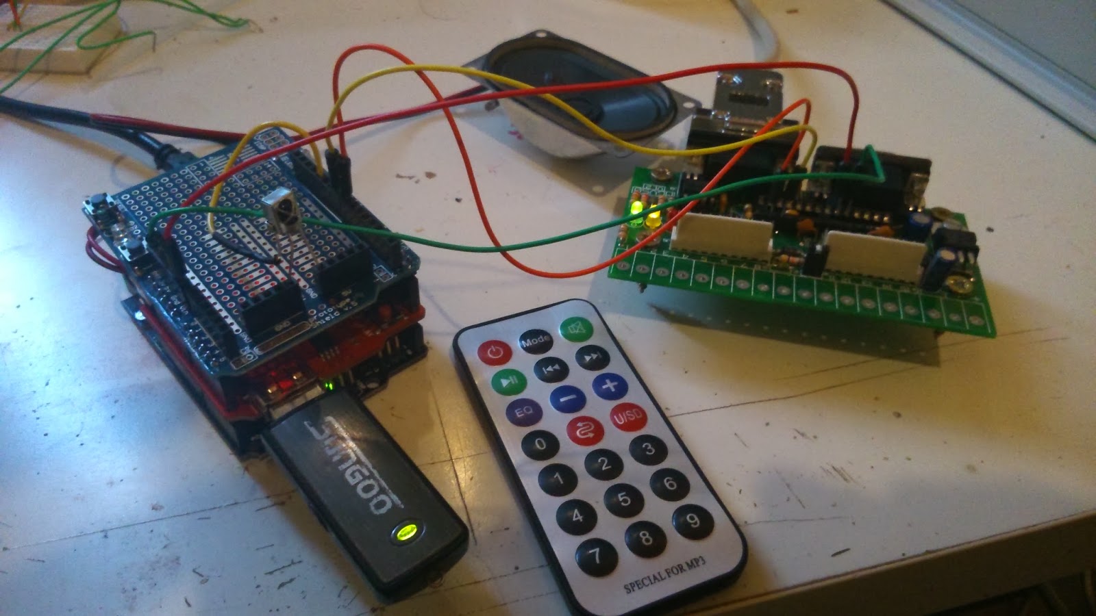


I tried to do a very simple project, able for those who don't know a lot about electronics (like me) or know nothing about programming. It's intended for Loconet digital layouts, but it's also possible to manage it from a standard remote control, so it can work also in analogical systems. I kept the existing functionality:
* Remote control for playing MP3 files, selecting the source (memory stick, SD card, internal memory), setting the volume and save settings.
* Assign MP3 files to output events. Whenever a defined output is activated (from hand throttle, main command station or software) its assigned sound is played
* NEW: Function keys from F1 to F4 for each individual locomotive can be also assigned to a sound, without loosing its functionality. I mean we can assign a horn or break sound to a locomotive's function key that is programmed to turn off the lights or set maneuver speed and the sound will play at the same time the function is executed. Each locomotive for each function key can have a personalized sound in each function key.
* NEW: Assign a sound to a locomotive that will be played when it stops in up to 10 configured segments. Of course this segments must be retro signaled. The main goal is to play an announce when the locomotive stops in front of the station, doesn't matter the track. So basically you configure up to 10 segments informed by loconet retro-modules, assign a sound to a locomotive and when it stops on any of these segments, it's sound is played.
May be you are asking yourself if you need any identification system to know whichlocomotive is the one stopped in the station... the answer is NO, but Arduino will know which locomotive has stopped, and will play it's personalized sound or announcement.
I will explain the tricky part with a very simple introduction of how Loconet communications work:
When you use a complete communication bus like Loconet in your layout, all kind of messages, signals and instructions are sent through the bus to all its components and modules. When an output is activated from your throttle, a message is sent through the bus to all modules saying "Output number X activate". This is received by all devices listening the bus, but of course just the module in charge of output X executes the command. The same happens when a signaling module detects consumption in a segment, it sends a message saying "My section number X has been activated". The software controlling the layout also receives it, and it can react stopping a locomotive or changing a light. And finally, in the bus you also receive all instructions sent to the trains, like changes of speed, activation or deactivation of functions, ...
And basically the software in Arduino "hacks" the network interpreting all kind of messages, in IT language it's a sniffer. When it receives a message informing the activation of one of the configured sections, pays attention to the first locomotive setting it's speed to zero. In this last message the number of locomotive is informed, so it assumes that locomotive is the one that has stopped in this section and therefore plays it's configured announcement or sound.
As it is an independent and passive system, not interfering in the communications, it doesn't need any kind of special configuration in the software, throttles nor locomotives. And it works in any Loconet layout with any software, command station and decoders. Also works in a full automated system or when we drive it manually.
The hardware construction is easy: buy an Arduino Uno, plug on it a MP3 shield from Elechouse and build your own Loconet interface or buy a GCA50 board from Peter Giling to have half of the work already done.
The software part is also easy: upload the program in arduino, and connect it to the USB. To set up the parameters there is a menu shown directly in the serial console of Arduino IDE:
Typing "config" the menu shows the options to set up the sensors (up to 10), Locomotives (up to 50), clear the memory and save settings.
When setting up a locomotive we just need to type the id number (same number we use in the throttle) and the function where we want to assign a sound. It can be any of the function keys (F1 to F4) or SENSOR. SENSOR means the sound that will be played when this loco stops on any of the 10 sections configured in the first option of the main menu.
As always, now I have to clean the source code and optimize some parts before publishing it. That's the boring part once you see it's already working..... XDDD
I hope you liked it and be useful for anybody else!!!! Cheers,
Wednesday, January 15, 2014
Station Announcer final project
Finally I have a stable version of the station announcer running in Arduino and suitable for both analog (through a remote controller) and digital systems (with Loconet bus). I'll try to explain everything in an easy way, but be careful, I won't be responsible for any damage or any mistake in explanations!!!
First of all, the list of materials:
How to upload a program to Arduino board:
IR Receiver connection:

First of all, the list of materials:
- Arduino UNO R3: About 15$ or less in ebay
- Elechouse MP3 shield with built in amplifier: 21.5$
- Remote controller and IR receiver: 6$
- pc speaker from an old PC (or new, did you ever used it???): 0$
- To make the Loconet interface, components are 5$ more or less, and you can mount it in a protoboard shield or use directly a GCA50 board from Giling Computer Aplications (5€). I'm working designing my own Loconet interface shield, but meanwhile Giling GCA50 does the job perfectly. Giling Boards
And now the pre-requisites:
- Download and install Arduino IDE software from here
- Take my source code from http://sourceforge.net/projects/hanasueki/files/. It's the .ino file. Store it in your PC, and open it from Arduino IDE
How to upload a program to Arduino board:
- Connect Arduino board with the USB wire to the PC
- Open the Arduino IDE and from there, open the source code downloaded from sourceforge (hanasuLNet_ino.ino)
- In Arduino IDE, select the serial port that has been installed (usually is the last one) in Tools -> Serial port
- Also select your arduino board (UNO) in Tools -> Board
- If you have the MP3 shield plugged: as the MP3 shield uses the same serial port as the PC connection, you have to put MP3 shield in sleep mode or the PC link will not work. There is a push button in MP3 shield named "Sleep", just push it 3 seconds.
- Now click the download button (round button with an arrow) in the IDE and wait the progress bar
- It's done!!!! If you have any problem, review Arduino help: http://arduino.cc/en/Guide/Windows
IR Receiver connection:
The IR receiver has three legs. One goes to the +5V pin, other to the GND pin, and the third one to the I/O number 11. Here you have a very good tutorial about IR: http://arduino-info.wikispaces.com/IR-RemoteControl
Now plug an USB or SD card to the MP3 shield and it's ready to work. Following the MP3 Shield instructions, you will see it's possible to copy files in the internal memory, so there's no real need of having a memory stick or SD card always connected.
The remote controller has various functions:
- MODE key selects the sound source (internal memory, memory stick or SD card)
- Volume controls
- Power button stores the current volume and mode values in the non volatile memory (it's like a "save config" button)
- With the number keys you can select a file number (in the order they were copied to the memory) and pressing the play button it will play the file.
- It's also possible to use the NEXT and PREVIOUS buttons to play directly the next or previous MP3 file
Here there is a video of the station announcer in action:
I'll continue in a new post for the Loconet part. Enjoy it!!!
Thursday, December 19, 2013
Station Announcer running in a protoboard
I'm still waiting my Arduino UNO to arrive, but meanwhile I did some successful tests with a NANO.
If you followed my previous posts, I tested an MP3 shield for Arduino communicating via hardware serial:
http://www.clubncaldes.com/2013/12/arduino-project-station-announcer.html
And later, I ran a Loconet serial monitor also on Arduino to intercept the Loconet bus messages:
http://www.clubncaldes.com/2013/12/station-announcer-loconet-interface-for.html
Now I joined both experiments and changed a bit the source code to play a different MP3 file assigned to each activated output. Each time an output is activated, I play the same MP3 file number. The speaker you see has been taken from an old computer:
I activate the output through Intellibox keyboard, but it also works activating an output from the computer.
Now I have to wait the Arduino UNO and the numpad, and make a clean source code. The goal is to activate a sound typing the sound number in the numpad or via Loconet assigning a digital output to each file.
I hope to post the final result soon!!!
If you followed my previous posts, I tested an MP3 shield for Arduino communicating via hardware serial:
http://www.clubncaldes.com/2013/12/arduino-project-station-announcer.html
And later, I ran a Loconet serial monitor also on Arduino to intercept the Loconet bus messages:
http://www.clubncaldes.com/2013/12/station-announcer-loconet-interface-for.html
Now I joined both experiments and changed a bit the source code to play a different MP3 file assigned to each activated output. Each time an output is activated, I play the same MP3 file number. The speaker you see has been taken from an old computer:
I activate the output through Intellibox keyboard, but it also works activating an output from the computer.
Now I have to wait the Arduino UNO and the numpad, and make a clean source code. The goal is to activate a sound typing the sound number in the numpad or via Loconet assigning a digital output to each file.
I hope to post the final result soon!!!
Sunday, December 8, 2013
Station Announcer: Loconet Interface for Arduino
Let's go for the second part of the project: Loconet Interface for Arduino.
I found a very interesting page talking about a Loconet Shield for Arduino. It's www.scuba.net (SPCoast, Railroading on the Southern Pacific Coast). They developed a shield for Arduino called LocoShield and wrote the needed libraries. In this page you can find all the information (electrical schema, Eagle files, Gerber files for fabrication...): http://www.scuba.net/wiki/index.php/LocoShield
And it looks like this:

The software (Arduino libraries and examples) are published in the MRRwA Project SourceForge Project: http://sourceforge.net/projects/mrrwa/
But unfortunately they don't produce the boards and nobody sells them, and the price to make just 5 or 10 is too expensive. Just if more people would be interested for a total production of 100 or more, then it would make sense. And I don't want to isolate my own boards because I never did it and I'm not skilled.
Another problem I saw is the power source. Arduino and MP3 Shield need 5Vcc to function and I can't take them from Loconet wires, and there is no 5Vcc power source supply in my layout... or there is? If I well remember, Peter Giling boards (the ones I use in my layout) have a different Loconet connector with the common signals of loconet plus 5Vcc to feed directly his interface boards through the same Loconet wire. GCA101 is the Ethernet-Loconet interface plus 3Amp power source of 5Vcc to feed all loconet boards (GCA50). So I have it!!!
Then, it would be greate to feed also Arduino from here and avoid more wires and power sources. Looking closer to the GCA50 electrical schema, it's almost identical to LocoShield from the Loconet DB9 connectors to PIC. The board feeds the PIC16F873 with 5Vcc taken from the DB9 Loconet connector, and converts the Loconet signal to a PIC readable TTL serial, exactly what I need also for Arduino and what LocoShield does.


Then that's the right solution: using a GCA50 board without the PIC as a Loconet interface for Arduino. I only have to mount the electronic components of the board from the DB9 connectors to the PIC. And I take the serial RX/TX signals and the +5V and ground signals from here to Arduino.
Just to test the idea, I took a GCA50 completed board and removed the PIC. Then I connected the RX/TX serial signals to pins 7 and 8 in Arduino (these are the pins used as soft serial by the LocoShield libraries):

I uploaded the Loconet Monitor program that comes with the Loconet libraries, and voilá!!! I can monitor all the traffic of the Loconet bus:

And now the job is almost finished. I can manage the MP3 shield through the hardware serial of Arduino, and read all the events of the Loconet Bus through a soft serial of pins 7 and 8.
In the next post, I'll show you everything integrated, running and playing the station sounds I want selecting an output in my Intellibox or my PC (Rocrail).
This post references and merits:
LocoShield: http://www.scuba.net/wiki/index.php/LocoShield
MRRWA (Model railroading with arduino): http://sourceforge.net/projects/mrrwa
Peter Giling boards: http://www.phgiling.net
Subscribe to:
Posts (Atom)