Tuesday, December 30, 2014

Installing servos in Peco turnouts

Some posts ago I showed how I wire Peco electrofrog turnouts. 
Hace unos cuantos posts mostraba como cableo los desvios Peco.


I also talked about the paper clips and using them as piano wires to move Peco turnouts:
También hable sobre el uso de los clips de papel como alambre o eje para mover los desvios Peco:


An today I would like to show the the complete process I follow to install a servo motor under a turnout. First of all, bend a paper clip in a "U" shape, with one arm longer than the other. Also mount servo in servo mount and screw the single arm to the servo. Before screwing the single arm (white plastic piece), make sure the servo is centered connecting it to the servo driver board. Y hoy me gustaría enseñar el proceso completo de cómo instalo un servo debajo un desvío. En primer lugar, se dobla un clip en forma de "U", pero dejando un brazo mas largo que el otro. Monta también el servo en el soporte y atorníllale el brazo sencillo. Antes de atornillar el brazo (la pieza blanca de plástico), hay que asegurarse que el servo está centrado conectándolo antes a la placa controladora de servos:


Put the paper clip in the servo as in the photo.
Se pone el clip en el servo como se ve en la foto.


Then bend the paper clip and cut the short side properly.
Después se dobla el alambre y se corta el lado corto a la medida.


That's the result before fixing it under the table. 
Este es el resultado antes de fjarlo bajo el tablero.


Put double sided tape on the servo mount to fix it easily under the table. This helps to keep the servo in place while we screw it to the table.
Poner cinta de doble cara sobre el soporte para poderlo fijar cómodamente bajo la mesa. De esta manera se puede atornillar luego sin que se mueva y se descentre el servo.


Before mounting it you have to remove the spring from the turnout in order to allow point blades to move freely. Of course you have drilled the needed hole before fixing the servo. Pass the clip through the hole of the throw bar and make sure servo and servo arm are aligned with the turnout. Also make sure point blades are in the middle of the movement, not touching any of the stock rails, and press the servo to the table. With the double sided tape it stays in place and you can screw it.


Antes de montar el servomotor hay que quitar el muelle del desvío para que los espadines queden sueltos. Por supuesto, antes de fijar el desvío se ha hecho el agujero necesario. Se pasa el clip por el agujero del tirante asegurandose que el servo y el brazo están alineados con el desvío y el movimiento que ha de hacer. Asegurarse que los espadines están en mitad de su movimiento, sin tocar ninguno de los contracarriles, y apretar el servo contra el tablero. Con la cinta de doble cara quedará fijado y se puede atornillar con seguridad a continuación.


Espero como siempre que os sea de utilidad. I hope this be useful!!


Wednesday, December 24, 2014

Control Bus

Summary


As a summary of my latest post, I was explaining there are several digital communication systems to send orders to trains (DCC, Selectrix, Motorola,...). All them are based in a Central Station that, with the help of a Booster, modules the electric current to send commands to the mobile decoders installed inside the locomotives. But DCC is by far the most common and widely used at least in N gauge, despite it isn't the best nor the most versatile.

Later we saw, because of the lacks of functionality of DCC, new feedback buses used to send back information to the Central Station from the Feedback Modules. An example of those buses are RailCom and  S88, but nowadays they are completely old-fashioned.


And before talking about the different elements that compose a digital layout, I think is mandatory to talk about the Control Buses. The election of the Control Bus is the key for a new installation. It acts as a backbone or central nerve system interconnecting all components together. That means, all components must be compatible with the Control Bus. So it's a restrictive selection and it will restrict us in the range of digital components that we can connect to the layout.

Distinct buses used in model railroading

Everybody jumps into digital world buying first of all the Central Station, but most people select it taking into account just visual characteristics like how many throttles it has, or if it has color screen, or tactile, ... when all this things (throttles and panel screens) are not really part of a Central Station. Also functions like the possibility of creating routes or move trains in an automatic way are evaluated, when again those functionalities shouldn't be in charge of the Central Station. The better approach for me would be to evaluate the compatibility with the different buses in the market, and therefore with the existing software and electronic components like feedback modules, output modules, servo management modules, sound modules, ... of course other characteristics like how many locomotives can drive at the same time or the current power should be also evaluated.

What is a Bus?


But before that, what is a Bus? Taking the definition from wikipedia: "a bus (from the Latin omnibus, meaning 'for all') is a communication system that transfers data between components inside a computer, or between computers. This expression covers all related hardware components (wire, optical fiber, etc.) and software, including communication protocols."

It means a Bus specifications covers and explains not only the physical medium used (cable, radio, WiFi, fiber optics, ...), type of connectors (USB, microUSB, SubD9, RJ12, ...), supported topologies..., but also the communication protocol, message formats, type of commands available and everything referred to the software and programming part.

Keys to select a Bus


There are dozens of distinct Bus in the market, and many manufacturers designed its own bus like an industrial secret, without sharing the specifications so only they can build peripherals and modules and become your only possible supplier, setting the prices they want. Of course these are the ones we have to avoid first.

Second, there are also other kind of Bus being created openly by groups of users, completely the opposite example than before. But in many cases all the hardware must be constructed by our own so you need a deep knowledge of soldering, isolating boards, electronics and programming. Usually it's a cheap but very complicated solution.


And the third big group of Bus we have to avid are those based in old-fashioned technology. As I see it, any kind of bus not based in a Peer to Peer architecture (see Peer to Peer information). In this kind of architectures or topologies Peer to Peer (more known as Networks, better than Bus) doesn't exist the figure of "master component" and "slave component", so all at the same time can send and receive information, produce or consume information, or be "master" and "slave" at the same time. The way of connecting the components (topology) is normally also very flexible:


So despite the communications with locomotives will be for sure DCC, the connection and dialog with the rest of components of the layour (PC, outputs, feedback modules, sound, lighting, ...) will be done through the Bus. That's why is so important the bus election over the central station, throttle or any other component.

My suggestion


I don't want to finish just here, without any specific advise or Bus recommendation. I know it's a personal election based in many factors like our skills (are we able to construct our electronic components?), likes (do we want to program our modules) and of course budget. But if I have to recommend a bus not knowing the particularities of a person I would suggest Loconet by far because it has all this characteristics:


  • It's a Peer to Peer type Bus
  • Very flexible form the topology side, it can be connected very simple in line, or using hubs and combine star and tree. 
  • The Bus is property of one manufacturer (Digitrax), but on the other hand specifications are public. Everybody can access to them and build and program they own modules and devices.
  • Supporte by multiple manufacturers. You are not restricted to Digitrax, also Uhlenbrok, Digikeyjs, Fleischmann, ...) make central stations, modules, throttles and all kind of devices for Loconet. 
  • DIY (Do-it-yourself) possible. If you like to program, and/or build and/or solder your own electronics, there's plenty of information to make your own digital system's components and shops to buy pre-made boards.
  • Arduino compatible. For me that's a personal must. It exists a Loconet shield called GCA185 that you can build or buy here, done by Giling Computer Applications. With this you can easily program your own throttles, fast clocks, outputs/input modules, sound modules, .... whatever!!!!


I don't want to state Loconet is the best option, just my recommendation knowing no details about the final user. That's the option I have despite if I would start again from scratch, may be I would choose C-BUS because I like to construct all my electronics.

But as I want this to be usefull, from now on I will talk just about DCC and Loconet combined, which seems the best option at least in a short/medium term.


Tuesday, December 23, 2014

History of Digital Systems

I would like to write some useful articles for those who want to step into the digital world of model railroading. It's not my intention to create the ultimate guide to digital systems, nor to cover all technical aspects and all kind of details. There are millions of much better pages out there and really specialized in concrete buses, wiring, lighting and each one of the different aspects of the digital railroad modelling world. My intention is just to create an introduction to that, and easy way to step into with no fears, so people used to analog layouts or completely novices feel safer and more confident to move to DCC world.


Iberama 570

Analog layouts and systems are quite old, with many years of experience, and nowadays there is no one inventing new things: one transformer for each aisle circuit, one train can move in each of these circuits, push buttons to change switches, electrical switches to light traffic lights and activate or deactivate current in a section... and some automation more or less complex (but simple) using relays, diodes or passive components. That would be the most common scenario for analog layouts.

More or less all problems or doubts have one good answer or way to solve them, and the number of elements and ways to solve it are really reduced in comparison to a digital system. Like said before, in analog you use simple electronic components like diodes, relays, switches, resistors, .... not much variety (taking as an example a simple or common layout). And you can mix easily components or products from distinct vendors.


Componentes electrónicos (fuente Wikipedia)

Digital world is not more complex (I think it's easier). A good example for me would be in telephony: modern smartphones aren't more complex to use than and old and analog one, if you use it just as a telephone!!! But as it has a lot more of functionality, options, vendors, operative systems, firmwares, connectivity, .... seems more difficult.

Same thing happens in digital railroading, and besides that it's still an immature market with no big standards set (just DCC as you will see or the ones from Digitrax manufacturer). There are lots of vendors, new brands every day, every one makes it's own systems not compatible with others trying to be the first setting a big standard, ... It's normal for someone starting to have so many doubts!!

And to start in a proper way, I think the better is a bit of history to know where one of the big standards called DCC come from.

If you read something about digital systems in railway modelling, for sure these three letters appeared everywhere: DCC (Digital Control System). Many times it's used in wrong way to talk in a general way about any digital train control system. But strictly speaking, it's the NMRA DCC; a communication protocol defined by NMRA (National Model Railroad Association) in 1993 which defines the communication system to send orders to the locomotives at both physical and electrical level. It defines a central station that, in conjunction with a booster, modulates the track current to encode digital messages at the same time that delivers current to the rolling stock. Inside locomotives a small chip (called Decoder) is installed in order to decode and understand those messages and act to the orders. So, here we have a bit difference in front of analog systems: digital tracks are always feeded with current, it doesn't matter if locomotives are moving or not. That also means more that one locomotive can be in the same section and it's not needed to create aisle sections for each locomotive. Because the orders to start, break or turn on the lights are sent personalized for each locomotive. Later on the different components of a digital system (central station, booster, decoder,...) will be better explained.

There are other protocols or digital systems to command trains like Selectrix (created by Döhler & Haas, bidirectional and based in a big industrial standard from Siemens) or Motorola, but now a days DCC is the leader of the whole market despite is the worst protocol ever thought. Yes, you read well. The ones who designed this protocol hadn't a wide view nor future vision, and created this protocol completely unidirectional, just from the central station to the locomotives. So you can send commands to the trains, but trains cannot answer any kind of information. Knowing this fact, you will easily understand later why you need a programming track to setup the decoders where locomotives have to move the motor to send acknowledge signals to the central station, or why you can configure a locomotive in the normal track but you cannot read the current configuration values.

So, with this protocol or system we were able to move locomotives, but we also wanted to command switches and lights. That's why a new kind of decoders appeared, called "static decoders" in front of "mobile decoders" (the ones installed inside the trains). Static decoders are connected to the rails' current and receive DCC commands to turn on/off switches, lights or any other device.

But not after a long period of time, the need of receiving information appeared. In order to automate the control of the layout from a computer software it was needed to know the occupancy of each section of the layout using any kind of sensor (consume sensors, reed contacts, light barriers....).

That's why in 2007 the NMRA included to the DCC norm a new extension called RailCom (developed also by Lenz and other manufacturers). They could have extended the already existing DCC to create a new bidirectional and compatible one, but again failed creating a parallel communication channel, and again unidirectional, from the sensors to the central station or directly to the PC. So you need to double the meters of wire needed in a layout for both unidirectional channels:


Fuente: Wikipedia

Here in Spain Railcom didn't become popular, but its competitor S88 from Märklin (a really similar systems for feedback modules) is still in use and widely used. The "boxes" connected to the physical sensors and sending the occupancy signals are called "feedback modules". So a common digital installation (I said common, not modern) is composed by the Central Station and booster, of course a throttle to set the speed and direction of locos, mobile decoders installed inside locomotives, stationary decoders to command switches and lights, and feedback modules to send occupancy detection signals to the main system (usually a PC).

Just to finish this brief review, DCC has an extra problem: as static decoders (those controlling switches, lights and outputs generally speaking) are connected to the track current, consumption can grow easily to be forced to buy another booster, which is an expensive element.

To solve that, and relatively new in this world, appeared the Control Buses. Static decoders and feedback modules as they are known until this time disappear, and everything (called just input or output modules) are connected together to a single communication line (bus) that shares completely all messages and information of all elements of a layout.

In next posts I will talk about Control Buses and a modern digital system approach using them as I understand this digital world.

Saturday, November 22, 2014

NEW ARDUINO LIBRARIES VERSION FROM MRRWA!!!!

A new version of MRRWA libraries has been released!!! Before making a brief summary of the project, I post directly the address to download them:


The main change I saw is in Loconet part, including an implmementation for LNCV config. And it is just perfect for my projects, so I can setup my programs from the Intellibox, Uhlenbrock PC software or Rocrail directly using this LNCV protocol. There is no need to dismount the Arduino when it's in place under the layout and connected, nor connect a USB cable to it for configuring or setup the application parameters.

Some review until this point:

Some months ago I posted some musings about Arduno used in a railroad layout and how to connect it to a Loconet network. I showed how to use a cheap GCA50 board to make an interface to connect Arduino to a Loconet network using the standard Giling Computer Applications connector that provides both loconet and power to feed the Arduino:


After that, a first prototype shield was designed and built by Peter Giling, called GCA185, which you can buy here: http://www.phgiling.net/


At this point, I did a program to turn Arduino in a Sound Module for ambient sounds in a station. It was able to be governed by a remote control (for analog users) and also to be configured to play a sound for each function key of each train or even detect a train stopped in a detection section to reproduce its announce. Here and here there's all the information.

But I wanted to implement a configuration protocol through Loconet to avoid dismounting the Arduino or connect a USB cable in order to configure it. I did it using the same GCA50 protocol, and copying its functionality but in an Arduino board. But that was not enough for bigger or different projects and programs.

Next step was implementing the LNCV protocol. That's the protocol used by Uhlenbrock to setup all his hardware and modules, but as everything from Uhlenbrock the information is strictly confidential. Rocrail was also implementing this protocol and I started looking at their source code. But suddenly a new version of Loconet Libraries for Arduino has been released, with LNCV protocol already implemented!!!!

BRAVO, BRAVÍSSIMO for MRRWA guys!! Congratulations and thanks so much to share your work!!!

Sunday, November 2, 2014

Saló del Manga de Barcelona


This weekend was held the annual Manga Festival in Barcelona. It's been the XX edition, bigger than ever with 50.000 square meters of exhibition, and beating again the assistance record in more than 130.000 people.


A funny thing happened in this performance, when the worst scene of Berserk was played by chance in the background, distracting the singer when everybody started laughing...


The exhibition was not only full of merchandising stands, but also Japanese food stands. There was a big stage performing concerts and karaokes, a lot of cosplay, and a good opportunity to buy (not a cheap price) manga, films, anime, t-shirts, books, figures, posters, .... whatever related to manga phenomenon.

This year the manga Shingeki no kyojin (進撃の巨人) was a top trend, despite it was dedicated to Pokemon.


And as every year, a lot of people disguised being for one day their favorite manga protagonist or hero.


Thursday, October 2, 2014

Ligne de Petite Ceinture (Paris)

Hello everybody! Last week I was in Paris visiting my sister. I always plan a "train related activity" when I travel abroad, if it's a pleasure trip. Some times it's just visiting train shops, others going to a museum, and others coinciding with a hobby flea market. But just some days before going I read somebody in a forum talking about an awesome abandoned circular railway inside of Paris. At the same time somebody sent me link to a site with incredible photos of abandoned places, and seemed to be the same old abandoned railway of Paris.


http://www.earthporm.com/21-photos-nature-winning-battle-civilization/


That couldn't be just a coincidence, I had to found that railway line!!! And yes, after some research I found this line is called Chemin de fer de Petite Ceinture (French for "little belt railway").


From wikipedia:

"...was a Parisian railway that, from 1852, was a circular connection between Paris's main railway stations within the fortified walls of the city. In a partial state of abandonment since 1934, the future of its yet-undeveloped property is the subject of much debate as of 2013. Many French railway enthusiasts and associations would like to see the abandoned railway and its remaining stations preserved and protected as a part of France's national heritage."

I also found there is a park called Montsouris in the south of Paris, crossed by the normal railway line and also with a visible part of the Petite Ceinture. Now I can assure the photo was taken exactly in this park, it's exactly the section of tracks passing the park Montsouris.


The park is awesome, with a big lake where many ducks, swans, turtles and many other animals live, big and old trees from all over the world and many place to make picnic. There are also some bars, a restaurant, kids playground zone, public toilets,... really nice.

And these are my own photos. As my camera was broken in a previous trip to Germany, I just had the mobile phone so the quality is really poor:


The line extends outside the park, may be in another trip I try to follow it and see if there is a point to go inside.

Cheers!!


Tuesday, September 2, 2014

Buses de Control

Como resumen del post anterior, explicaba que existen varios sistemas de comunicación con los trenes (DCC, Selectrix, Motorola,..), y se basan en una Central que con un Booster modula la corriente eléctrica para enviar comandos a las locomotoras, que a su vez tienen instalado un "chip" que lee estos comandos y actúa según las instrucciones recibidas. Pero no hay que pensar mucho cuál escoger según mi opinión, porque el DCC se ha hecho con la mayoría del mercado (al menos en la escala N) aunque no sea el mejor ni el mas versátil.

Luego vimos que debido a las carencias del DCC aparecieron otros buses muy sencillos para enviar información en sentido contrario (de los retromódulos a la central) como el RailCom y el S88. Pero actualmente también están totalmente desfasados, sobretodo el S88 que no tiene ni sistema de control de errores.


Y creo que de lo siguiente que hay que hablar a la fuerza es de los Buses de Control, antes de entrar ya de lleno en diseccionar los distintos elementos de los que se compone una maqueta digital. ¿Y por qué? Pues porque actualmente todo planteamiento de un sistema digital se basa en un Bus de Comunicaciones central por el que se comunican los diferentes elementos de la maqueta. Y todos los elementos, han de ser compatibles con este tipo de bus.

Logotipos de diferentes buses actuales

Así, en lugar de elegir en primer lugar la central digital que mas nos guste (y por aquí suele empezar todo el mundo), creo que el acercamiento mas correcto es elegir en primer lugar el Bus de comunicaciones. Para elegir el bus hay que examinar sus prestaciones, compatibilidad de fabricantes, número de centrales, módulos y retromódulos compatibles, prestaciones, compatiblidad también con los distintos softwares de control disponibles...

Pero antes de nada... ¿qué es un Bus? Citando wikipedia: "En arquitectura de computadores, un bus es un sistema de comunicaciones que transfiere datos entre componentes dentro de una computadora, o entre computadoras. Esta expresión engloba todos los componentes de hardware relacionados (cable, fibra optica,  etc.) y software, incluyendo los protocolos de comunicación."
Esto significa que en un bus se define el medio físico; tanto por dónde enviamos los datos, como ahora dos cables, ondas en el caso de la radio o la wi-fi, fibra óptica..), como los tipos de conectores usados (USB, microUSB, SUBD9, RJ12, ...) y cualquier otra característica física como las topologías soportadas.
También se define el protocolo de comunicaciones o dicho de otra manera, cómo circulan los datos por este medio físico y qué comandos tiene o cómo se forman los mensajes que se pueden enviar y recibir y todo lo referente al software y a la programación para poder enviar y recibir ordenes/comandos/mensajes.

Hay decenas de buses en el mercado, y muchos fabricantes han diseñado el suyo propio del que se guardan recelosos las especificaciones y protocolos como un gran secreto industrial para que todos los elementos de la maqueta se le tengan que comprar a él. Estos son de los primeros de los que tendríamos que huir por la falta de compatibilidad y versatilidad que nos puede ofrecer un único fabricante a menos que estemos totalmente seguros que sus productos cubrirán todas nuestras expectativas y estemos dispuestos a pagar sus precios.

En segundo lugar hay otra serie de buses que han creado grupos de usuarios y son totalmente abiertos y públicos, pero que en muchos casos todo el hardware tendrá que ser fabricado por nosotros mismos. A menos que tengamos grandes conocimientos tanto de electrónica como de programación, son una opción complicada.


Y el tercer tipo de buses del que tenemos que huir, son los basados en tecnologías antiguas. A mi entender, cualquiera que no esté basado en una arquitectura Peer to Peer (ver información de Peer to Peer). En las arquitecturas Peer to Peer (que se llaman Redes, mas que Buses) no existe la figura de un componente en la Red o el Bus que es "la cabeza" o "el master" y el resto que son "esclavos" o simples "oyentes"; al contrario, todos a la vez son "masters" y "esclavos", o dicho de otra manera, cualquiera de ellos se puede comunicar con cualquier otro o todos a la vez y enviar información a la vez de recibirla. Además ofrecen una topología ("manera de conectar") muy flexible, permitiendo enlazar todos los elementos uno detrás de otro (en línea), en estrella, arbol, o una combinación de varios de ellos:


Con esto se puede ver la gran importancia del Bus de comunicaciones (dejando de banda la comunicación DCC con las locomotoras, aquí repito que para mi no hay otras opciones válidas que no mejores), y cómo de fatal podría ser el error de elegir una Central porque es "chula" o está bien de precio y que nos obligue a usar un Bus de datos poco fiable, con pocas opciones de compra o que a largo plazo puede ser extremadamente caro.

No quiero dejar el tema tan abierto para que todo el mundo siga pensando "vale, muy bonito, pero qué bus utilizo?!?!?". Así mi recomendación personal, que creo que es la que mejor se puede adaptar a todo tipo de ferromodelistas, es Loconet:

* Es un bus tipo Peer to Peer
* Muy flexible en cuanto a la tipología, permite desde una simple y en línea hasta la utilización de concentradores y combinar con estrella o árbol
* Hay acceso a las especificaciones técnicas del Bus. Es propiedad de un único fabricante (licenciado a Digitrax), pero el protocolo es público. A nivel particular se puede acceder a las especificaciones y uno mismo programar o construirse lo que quiera.
* Múltiples fabricantes. Han cedido o vendido licencias a otros fabricantes para que sus elementos (Centrales, mandos de control, retromódulos, módulos de salidas, sonido...) sean 100% compatibles con Loconet.
* Opción de DIY (Do-it-yourself). Si os va el bricolaje y fabricaros vuestras propias placas electrónicas y módulos, hay muchos diseños publicados en internet.
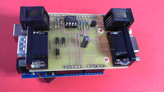
* Compatible con Arduino. Para mi lo que mejor de todo, existe un shield Loconet para Arduino (Giling Computer Applications) con lo que cualquier Arduino podemos programarlo para que haga de retromódulo, de módulo de salidas, hacernos un mando propio, un fastclock, o cualquier otra cosa que se nos ocurra.

No quiero decir que sea absolutamente la mejor opción y la gran panacea, pero yo es la que tengo y la que recomiendo. He de confesar que si comenzara de nuevo, y porque me gusta mucho fabricarme yo mismo las cosas, utilizar Arduino y soy programador, tal vez escogería un C-BUS contradiciendo lo anteriormente dicho.

Pero como se trata de enseñar algo práctico, y en lo que se haya tenido experiencia y no sólo teoría, a partir de ahora hablaré de la combinación que yo conozco: DCC y Loconet


Friday, August 29, 2014

Historia de los Sistemas Digitales

Hola, Hello!! I'm sorry but I'll be writing some posts about Digital Systems in Spanish. The fact is that I'm receiving many questions from Spanish colleagues asking many questions about it, and is easier to send a link than writing every time the same answer to similar questions. Most of them have been always in analog systems and now are a bit scared to change to Digital, so I'll write some articles explaining the main concepts and main components of a digital system, a bit of history, how to plan a Digital Layout, existing solutions in the market... but I promise to translate them also in my poor English (sorry about that...).

Bien, como declaración de intenciones me gustaría escribir algunos artículos que fueran útiles para aquellos que dominan perfectamente una maqueta analógica, pero no conocen en qué consiste un sistema digital ni como iniciarse en él. No pretendo nada ambicioso, ni que esto sea la gran guía del digital, ni cubrir absolutamente todas sus funcionalidades y opciones. Simplemente me gustaría que quien lo lea pierda cualquier miedo al digital, no lo vea como algo mas complicado que el analógico, y por fin dé el primer paso con confianza a entrar en este mundo.


Iberama 570

Los sistemas analógicos tienen muchos años de existencia y ya no hay nadie inventando muchas cosas nuevas; un transformador para cada circuito aislado de vías, sólo puede moverse un tren a la vez por cada circuito, pulsadores para cambiar desvíos, interruptores para encender semáforos y activar o quitar corriente a un tramo de vía... y unas pocas automatizaciones mas o menos complicadas que pueden hacerse mediante relés y diodos para que al encender un semáforo se active también la corriente a la vía y cambie un desvío o similar.

Casi todos los problemas o dudas tienen una única respuesta, y el número de elementos que lo componen y las maneras de montarlo son muy reducidas en comparación a un sistema digital. Como decía, básicamente en analógico se juega con componentes electrónicos simples tipo diodos, relés de varios tipos, pulsadores o interruptores, leds, un transformador para alimentar las vías... y no hay mucha variedad mas (hablando siempre de lo básico o mas estandard).

Componentes electrónicos (fuente Wikipedia)

Digital no es que sea mas complicado (yo pienso que es mucho mas fácil), lo que pasa es que hay muchos fabricantes y cada uno hace sus montajes a su medida y vende material no compatible con los demás, a veces utilizan nomenclatura distinta, y todavía no ha dado tiempo a que se establezca un único estandard. Así pues, entre la variedad de estándares, fabricantes, sistemas, y la rápida evolución que todavía está haciendo el mundo digital (de los trenes en miniatura) alguien que quiera introducirse de nuevo no sabe por dónde empezar.

Y precisamente para comenzar, yo creo que lo mejor es un poquito de historia para saber de dónde venimos. No de todos los sistemas digitales existentes, pero sí por lo menos del mas conocido: el DCC

Supongo que a todo el mundo le suenan las siglas DCC (Digital Control System), sobretodo porque se utiliza para referirse de manera genérica a cualquier tipo de sistema de control digital de trenes, pero hablando estrictamente, es el NMRA DCC; un protocolo definido por la NMRA (National Model Railroad Association) sobre el año 1993 y que define el sistema de comunicación con las locomotoras tanto a nivel eléctrico como de comunicaciones. Sin entrar en mas detalles define una Central que junto con un Booster modula el voltage de la vía para codificar mensajes digitales a la vez que suministra la corriente eléctrica. En las locomotoras se instala un pequeño "chip" (Decoder) que interpreta estos mensajes y actua en consecuencia. Aquí tenemos una primera gran diferencia: las vias en Digital siempre tienen corriente y lo que se hace es mandar mensajes a las locomotoras para indicarles que arranquen, paren, aceleren o enciendan las luces. Entraré mas adelante en los componentes de un sistema digital, así que por el momento no os preocupéis en entender exactamente qué es un Booster o una Central.

La gran pega de este protocolo (según mi opinión) es que no tuvieron una visión muy amplia, y sólo definió la manera de enviar señales a las locomotoras. Así que este protocolo es unidireccional, sólo van mensajes desde la Central (desde donde nosotros controlamos los trenes) hacia las locos, pero no pueden ir mensajes en sentido contrario. Con esta versión original del DCC ya se podían manejar las locomotoras, pero los desvios, semáforos,... etc. se manejaban tradicionalmente.

A esto se incorporaron un tipo de Decoders similares a los que necesitaban las locomotoras pero que recibían órdenes para manejar desvíos o semáforos. Comunmente se les llama Decoders Estáticos en lugar de Decoders Móbiles (los de las locomotoras) e iban también conectados a la corriente de las vías de donde recibían las instrucciones. Pero luego se dieron cuenta de la necesidad de no únicamente enviar instrucciones a los elementos de la maqueta, sino también de recibirlos para conocer por ejemplo la velocidad actual de la locomotora o para poder poner sensores en las vías y conocer en qué punto del trazado esta un tren en ese momento.

Por este motivo en 2007 la NMRA incluyó a la norma DCC una extensión llamada RailCom (también desarrollado por Lenz junto con otros fabricantes) y que es otro canal de comunicación, pero en sentido contrario. Por este canal se recibe la información de cuando un tramo de vía está ocupado o libre, pasando del primer esquema sencillo a este segundo en el que hay que hacer una tirada de cables especial para los sensores de ocupación:

Fuente: Wikipedia

Al menos en España este Railcom no ha sido muy popular, pero en cambio se extendió enormemente el S88 de Märklin, que viene a ser lo mismo. Se utilizan otros cables y no los de la vía para comunicar los retromódulos con la central y que esté informada de las secciones de vías ocupadas y libres.

Pero no creáis que DCC es el único protocolo existente para manejar los trenes, por ejemplo también existe el Selectrix, creado por Döhler & Haas. Este protocolo está basado en un gran estandard industrial de Siemens y permite comunicación en ambos sentidos y manejar absolutamente todos los elementos de la maqueta. Pero esto es parecido a la lucha entre los sistemas Beta y VHS o el BluRay y el HD DVD mas recientemente, muchas veces no gana ni se hace popular el mejor. Hoy en día es DCC el que está mas implantado y creo que no vale la pena mirarse ningún otro.

Ya para acabar, al DCC se le suma otro problema, y es que los decoders estáticos (para controlar desvios, semáforos...) utilizan la misma corriente de la vía que las locomotoras, haciendo que el consumo sea bastante elevado según el número de elementos que tengamos. A partir de aquí, y desde hace relativamente poco, han nacido los Buses de Control. Con estos buses de control que ahora veremos la corriente de las vías se utiliza únicamente para alimentar y enviar instrucciones a los trenes, y todo el resto de elementos para controlar desvíos, desengaches, luces, semáforos, sonidos de ambiente... se conectan y alimentan del Bus. Incluso la central de control pasa a ser un elemento mas "pinchado" o conectado al Bus. Es este Bus el que se convierte en la "espina dorsal" o en la "autopista de comunicaciones" de absolutamente todos los elementos de la maqueta. Y toda la potencia de nuestro Booster se dedica exclusivamente a dar corriente a los trenes, nada mas.

En un siguiente post, hablaré de estos Buses de control y los elementos que componen un sistema Digital moderno. Hasta entonces, espero que este artículo os haya parecido interesante.

Thursday, August 28, 2014

My layout plans

Hello, I would like to share my layout plans. They changed a little bit during the process of construction, not much, but I simplified some parts for a cleaner and more practical sketch. I removed one of the tracks of the main station and simplified a lot the internal part of the second and main level. Third level has very narrow curves, so I had to sacrifice the double track and go back again to a single track route. On the other hand, I added a dead track on the right of the main station.

Let's start with the zero level, mainly hidden and with a feedle yard, with no changes:


This is the most visible part of the layout, with a main station, two tracks for container platforms with a crane in the right part of the station, an industrial area (on top of container area) and a rural goods platform at the end of the internal track:


And the top and third level of the layout, accessing a small station to access the shrine and bath houses:


This is the complete layout, planning where to put the electronic devices, boards and controllers:


Thursday, July 3, 2014

Nice spot leaving Kyoto

I just would like to share some photos taken from the train just leaving Kyoto station to Kansai Airport. Close to Kyoto station there is the Umekoji Steam Locomotive Museum (梅小路蒸気機関車館 Umekōji Jōkikikansha-kan) and a container cargo platform next to it.

Here you can see the exact localization:


I think the steam locomotives of the photo are a C61 and a C55, and in the background you can see the 20 track roundhouse built in 1914:


I love those Koki flat cars and all those small 12-foot containers used in Japan. I hope you like the following photos, and may be they are inspirational for any weathering work in your layouts: