- 2-byte and 4-byte locomotive addressing
- 128-step speed throttling
- Activate/de-activate all accessory function addresses 0-2048
- Programming on the Main Operations Track
- write configuration variable bytes
- set/clear specific configuration variable bits
- Simultaneous control of multiple locomotives
- Control of all cab functions F0-F28
- Programming on the Programming Track
- write configuration variable bytes
- set/clear specific configuration variable bits
- read configuration variable bytes
But the best thing is that it will only cost you 8$ using the basic Arduino UNO, or 12$ using a more powerful Arduino MEGA. Yes, just 8$!!!! I suggest you to use Arduino MEGA in view of future expansions I want to implement, like a Loconet bus or the possibility to work in digital and analog mode. Don't be afraid about the difficulty to mount the system, you DON'T NEED to solder anything, just plug, upload the program, and run!!!
HARDWARE
To mount this command station you need the following hardware:
Arduino MEGA: It can be found in ebay for 8$, I bought it here. Arduino UNO is also suitable, but I prefer a MEGA board as it is faster and more expandable.

Arduino Motor Shield R3: It will not cost you more that 5$ in ebay, here is where I bought mine.

12 Vcc power supply: I use a power source from an old computer (yellow and black wires provide 12Vcc), but any power source with at least 2Amp can be used. For H0 scale, is better a 15Vcc power source, but for N scale 12Vcc is enough.
SOFTWARE
And the following is the needed software to make it run and manage and program trains:
Arduino IDE: This software is used to program Arduino or upload any already made software/firmware (or sketch in Arduino language) to the board. It will be used only once to upload the DCC++ command station sketch to the Arduino board, or in the future to upload a new program version with more features. It can be freely downloaded from Arduino official page: https://www.arduino.cc/en/Main/Software
Base Station DCC++: This is the software or firmware/sketch we will upload into Arduino board using the previous Arduino IDE. Just download and extract it in any folder in your computer. It can be downloaded from DCC++ page or directly clicking here.
JMRI: This is the program that "talks" to the command station and allows you to drive trains, move switches, program decoders, ... I plan to change the DCC++ command station protocol to make it more standard and be able to use also other software like Rocrail, but for now it must be used with JMRI. Download this software from http://jmri.sourceforge.net/download/index.shtml and install it. Under "Production Release" section of this page there are JMRI versions for Windows, Linux and Mac OS. This is a very good software, and freeware, and many times I use it to program decoders better than other software.
HOW TO MOUNT IT
Before mounting the Motor Shield r3 on top of Arduino, you have to cut the pad labeled "Vin" in the bottom of the board. This is to isolate the power input of the shield from the 12V power source that Arduino is also providing:
Now you can plug the motor shield board on top of Arduino. There is only one position how the motor shield fits on top, and pins are numbered in both boards, so just make sure pin 0 of the motor shield is connected to pin 0 of Arduino board.
I you are using an Arduino UNO, you have to bridge pin 10 and 12 in the motor shield (blue wire in the following photo), and pins 5 and 13 (red wire):

In case of Arduino MEGA, only one bridge is needed between pin 2 and pin 13:

Connect your 12Vcc power source to the screw terminals of the motor shield. Positive is connected to the screw terminal "VIN", and ground to "GND".
In the same screw terminal block, "A+" and "A-" are connected to your main track, and "B+" and "B-" to the programming track.
Connect Arduino to the PC with a USB cable. Probably your Arduino already came with it. Your PC should recognize then a new serial port.
Now we will upload the firmware (or sketch in Arduino terms) to the board. Go to the folder where you extracted the Base Station DCC++. Inside the "DCCpp_Uno" folder double click the file named "DCCpp_Uno.ino".

This will automatically open the Arduino IDE. You have to set up your connected Arduino board under "Tools" menu, option "Board". And also select the serial port as your computer detected Arduino when connected. This is also under "Tools" menu, option "Port":

Now everything is ready to upload the program, and to archive that you only need to click the upload button on the top left corner. After some second you should receive a message saying "Program uploaded" if everything went ok:

HOW TO USE IT
To set up JMRI to work with your brand new command station, just follow these instructions: http://jmri.sourceforge.net/help/en/html/hardware/dccpp/index.shtml
And you are ready to test your system. First of all, go to "Power Control" option inside "Actions" menú. Click the power on button of the new opened window, and led on the motor shield should light on if everything is correct. Now you can open a throttle, put a locomotive on the track, select its address, and push the throttle up!!! There is also a very good utility in JMRI to monitor the power drained by the track:

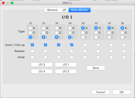
Now also Rocrail is compatible with this command station, and allows to use the other pins as input or outputs with the standard sketch from DCC++. You can use a connector to allow up to 4 GCA boards to be connected to the command station:

Even more, Rocrail has a special slot management with passive slot purge after 30 seconds idle and speed zero and it is compatible also with the Ethernet connection of DCC++ command station.
You can read all the information regarding the use of DCC++ command station with Rocrail here:
Enjoy it, now you have the best price/quality relation command station!!!!
Just an update, now Rocrail also supports this command station with protocol "dccpp"!!!!
ReplyDeleteHi Dani,
ReplyDeleteBrilliant article. I have a question; Do you need a separate programming track or can you use the main track as a programming track.Thanks
Thanks! You have both options: using the main track you can only set values for CV (not possible to read CV) as usual. It has and independent programming track where you can read and write CV in different modes (byte, register, ...). Everything like a "real" command station. ;)
DeleteThanks......I have just purchased the Arduino Mega and Motor shield.
ReplyDeleteI am in the process of building my Layout so it might be a while before I fire up the Command station.:)) One quick question which you might be able to answer; I want to install sensors on my track to determine when I operate a turnout, any recommendation which sensor works best. I know you mentioned the REED relay in one of your articles.
Hi, I use current sensors for track as they don't need any modification in rolling stock like reed. GCA93 from Peter Giling is the best option in my opinion. For turnouts I use servo motors (I don't like solenoid switches), and I manage them with GCA136+GCA137, also from Peter. Those boards manage the servo motor, feed the turnout frog, and also send a signal to the software (like a sensor) to indicate the position and when is the turnout in movement. All those boards (GCA93, GCA136+GCA137) need to be connected to a GCA50 board if you are using Loconet.
DeleteSoon I'll release a version of the DCC++ command station with my own modifications to be compatible with Loconet, so you can mount all the system in a Loconet bus and you can mix any command station or module if all them are Loconet compatible.
Hi Dani,
ReplyDeleteAre the Arduino boards (Mega and Motor Shield) LOCONET compatible. I have been reading about Loconet and it seems quite interesting. Any idea how much the Peter Gilling boards costs.
Also, how can you control the turnout even though you have a train on the track.....Thanks in advance.
Hello, no, they aren't. The original project from DCC++ has it's own interface and protocol to the PC though the USB connector of the Arduino board.
DeleteBut I'm changing it to make it compatible with Loconet, so you can add a Loconet Shield (GCA185) and becomes a command station compatible with any software.
I'm still working on it, but I have an operative version that allow to move trains and manage functions, just the programming of CV is still missing. The beta version is in github: https://github.com/ClubNCaldes/LNetDCCpp
As soon as I finish it I'll write a post with all the detailed information.
Dani, How much are the Peter Gilling boards. I was reading about the boards last night and it was not clear whether the boards can be purchased ready assembled?
ReplyDeleteAlso, regarding current sensing, how do you control the turn out to open or close if you have a train on the track. Sometimes you would want the train to move in a different direction.
GCA185 (Loconet shield from Peter Giling) is 6,75€ board only, or 19€ board plus connectors and cable (not mounted). It's not possible to buy it already mounted, but soldering of components is extremely easy.
DeleteYou can check all prices in his webpage:
http://wiki.rocrail.net/doku.php?id=gca:gca-index-en/
Dani, do I need the GCA 185 board as well.
ReplyDeleteYou don't directly need it. You can manage the command station connecting it through the USB connector to the PC. Both Rocrail and JMRI are compatible.
DeleteBut if you add a Loconet Shield with the software I'm currently developing for Arduino, you can connect it to the Loconet Network and manage it through your current PC interface, being compatible with any soft. But this software is not yet finished, in some months I'll have Loconet shields and software ready.
Thank you
ReplyDeleteOne correction: 12Vdc seems too low current for N scale, currently I'm using 15Vdc. With less voltage some sound decoders seem not to work.
ReplyDeleteSo am I to assume that these loconet boards, digitrax, canbus etc. That I can use a digitrax controller, nce controller etc while using the Arduino command station to control my trains?
ReplyDeleteThis version (DCC++ official version) is not compatible with standard communication buses. If you want a Loconet compatible version, I developed a new version. Information can be found here:
Deletehttp://www.clubncaldes.com/2017/04/cheapest-dcc-command-station-with.html
Hi, I intend using JMRI with DCC++ command station (Arduino). How can I interface multiple sensor inputs into JMRI without sacrificing an Arduino inout for every sensor input?
ReplyDeleteSorry Erik, but this would be a question better for the Arduino forum, there are different solutions for that. I know there are multiplexers to "multiply" the arduino pins, but I have no experience on that. Cheers!
DeleteThis comment has been removed by a blog administrator.
ReplyDeleteHello, I bought the arduino and motorshield according the recommended websites and the trains are runnning! THanks!
ReplyDeleteOnly 1 question. When I connect a DCC sniffer, the sniffer won't see any command from the main track. Programming track all commands are shown. With a ORD-3 the sniffer see every DCC commmand. Can you help me out? I've got troubles with a Arcomora DCC decoder and I expect that it comes that the main track has "invalid" DCC signals.
Can you help me?
Hi! I'm not skilled enough to snif DCC packets and work at so low level.... but if trains are moving... means these packets are there! But if you see the DCC packets in the programming track, seems more to be a connection problem than a software or configuration problem. Ask me if I can help you in a better way. Cheers!
DeleteHI there how would i go about adding analogue controls fro this rather than a laptop.
ReplyDeleteI would like a very simple setup using a center detent potentiometer to move forward and backward and a number of press buttons for the sound functions. any help or where to look would be helpful thanks
Hi, it would be a good idea indeed. You can use a potentiometer and some buttons, or even a IR remote. But I added a Loconet interface to the basic software of DCC++, and what I built is an independent loconet throttle to manage trains. Go ahead and tell me!! Cheers,
ReplyDeleteUno R3 and Motorshield lights are all on and working, but nobody's home :-(. Supply voltage is 15v, but A+ & A- and B+ & B- are only showing 0.05v.JMRI works with NCE (when enabled) and DCC++ looks like its working fine, but the loco just sits there. Any help appreciated.
ReplyDeleteSorry for my so late answer... but if motor shield leds are lighted and no supply voltage is out of the board, seems a problem with the board. Can you try with a new motor shield board?
DeleteI am only getting 025v out to track if I remove the jumper I get 12v out
ReplyDeleteCan I use an L293 instead of the REV3 shield. If so can you explain connections
ReplyDeleteThanks, Steve
I'm not sure, I just tried the components I describe in this post, sorry! Try to ask in the official DCC++ forum.
DeleteHi thanks for all info very intuitive. I have a test loco with R8249 decoder the Mega plus shield r3 and loco is only running at half speed. 12vdc 2amp psu connected to shield. 16vac at track. Any suggestions to why decoder is only giving 6vdc to loco motor please? Thank you
ReplyDeleteHi, I realized that 12V to feed the motor shield is not enough for some decoders. Try a 16V power supply for better results. I hope this works!!
DeleteHi great intuitive info thank you. I have set up using Mega R3 shield 12vdc 2amp PSU. I get 16vac to track but decoder is only giving about 6vdc to motor of loco. The loco has a R8249 decoder. Any ideas please as to why the motor is only getting 6vdc please? Thank you.
ReplyDeleteI hope someone can update this web page from 2015. As I write this it is 2022 and DCC-EX has taken this abandoned project and completely revamped it with significant improvements. EX-CommandStation does not require any jumpers and there are customizations in JMRI, Engine Driver, and other throttles and software to take advantage of the enhancements. Please see https://dcc-ex.com
ReplyDelete