Monday, February 22, 2016

Build your own DCC Command Station for 8$

I want to share here the information from DCC++ (https://sites.google.com/site/dccppsite/home) to build a DCC command station using Arduino. It is a complete DCC command station, supporting the full set of NMRA Digital Command and Control (DCC) standards, including:

  • 2-byte and 4-byte locomotive addressing
  • 128-step speed throttling
  • Activate/de-activate all accessory function addresses 0-2048
  • Programming on the Main Operations Track
  • write configuration variable bytes
  • set/clear specific configuration variable bits
  • Simultaneous control of multiple locomotives
  • Control of all cab functions F0-F28
  • Programming on the Programming Track
  • write configuration variable bytes
  • set/clear specific configuration variable bits
  • read configuration variable bytes

But the best thing is that it will only cost you 8$ using the basic Arduino UNO, or 12$ using a more powerful Arduino MEGA. Yes, just 8$!!!! I suggest you to use Arduino MEGA in view of future expansions I want to implement, like a Loconet bus or the possibility to work in digital and analog mode. Don't be afraid about the difficulty to mount the system, you DON'T NEED to solder anything, just plug, upload the program, and run!!!


HARDWARE


To mount this command station you need the following hardware:

Arduino MEGA: It can be found in ebay for 8$, I bought it here. Arduino UNO is also suitable, but I prefer a MEGA board as it is faster and more expandable.


Arduino Motor Shield R3: It will not cost you more that 5$ in ebay, here is where I bought mine.


12 Vcc power supply: I use a power source from an old computer (yellow and black wires provide 12Vcc), but any power source with at least 2Amp can be used. For H0 scale, is better a 15Vcc power source, but for N scale 12Vcc is enough.


SOFTWARE


And the following is the needed software to make it run and manage and program trains:

Arduino IDE: This software is used to program Arduino or upload any already made software/firmware (or sketch in Arduino language) to the board. It will be used only once to upload the DCC++ command station sketch to the Arduino board, or in the future to upload a new program version with more features. It can be freely downloaded from Arduino official page: https://www.arduino.cc/en/Main/Software

Base Station DCC++: This is the software or firmware/sketch we will upload into Arduino board using the previous Arduino IDE. Just download and extract it in any folder in your computer. It can be downloaded from DCC++ page or directly clicking here.

JMRI: This is the program that "talks" to the command station and allows you to drive trains, move switches, program decoders, ... I plan to change the DCC++ command station protocol to make it more standard and be able to use also other software like Rocrail, but for now it must be used with JMRI. Download this software from http://jmri.sourceforge.net/download/index.shtml and install it. Under "Production Release" section of this page there are JMRI versions for Windows, Linux and Mac OS. This is a very good software, and freeware, and many times I use it to program decoders better than other software.


HOW TO MOUNT IT

Before mounting the Motor Shield r3 on top of Arduino, you have to cut the pad labeled "Vin" in the bottom of the board. This is to isolate the power input of the shield from the 12V power source that Arduino is also providing:


Now you can plug the motor shield board on top of Arduino. There is only one position how the motor shield fits on top, and pins are numbered in both boards, so just make sure pin 0 of the motor shield is connected to pin 0 of Arduino board.

I you are using an Arduino UNO, you have to bridge pin 10 and 12 in the motor shield (blue wire in the following photo), and pins 5 and 13 (red wire):


In case of Arduino MEGA, only one bridge is needed between pin 2 and pin 13:


Connect your 12Vcc power source to the screw terminals of the motor shield. Positive is connected to the screw terminal "VIN", and ground to "GND".

In the same screw terminal block, "A+" and "A-" are connected to your main track, and "B+" and "B-" to the programming track.

Connect Arduino to the PC with a USB cable. Probably your Arduino already came with it. Your PC should recognize then a new serial port.

Now we will upload the firmware (or sketch in Arduino terms) to the board. Go to the folder where you extracted the Base Station DCC++. Inside the "DCCpp_Uno" folder double click the file named "DCCpp_Uno.ino".


This will automatically open the Arduino IDE. You have to set up your connected Arduino board under "Tools" menu, option "Board". And also select the serial port as your computer detected Arduino when connected. This is also under "Tools" menu, option "Port":


Now everything is ready to upload the program, and to archive that you only need to click the upload button on the top left corner. After some second you should receive a message saying "Program uploaded" if everything went ok:


HOW TO USE IT


To set up JMRI to work with your brand new command station, just follow these instructions: http://jmri.sourceforge.net/help/en/html/hardware/dccpp/index.shtml
And you are ready to test your system. First of all, go to "Power Control" option inside "Actions" menú. Click the power on button of the new opened window, and led on the motor shield should light on if everything is correct. Now you can open a throttle, put a locomotive on the track, select its address, and push the throttle up!!! There is also a very good utility in JMRI to monitor the power drained by the track:


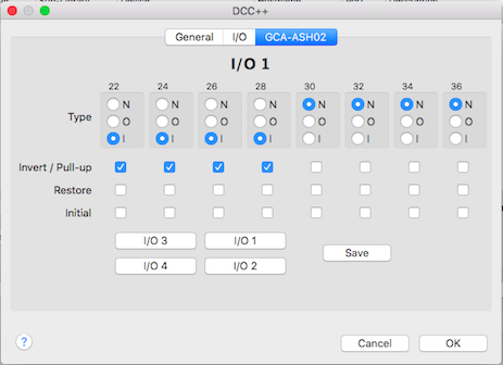
Now also Rocrail is compatible with this command station, and allows to use the other pins as input or outputs with the standard sketch from DCC++. You can use a connector to allow up to 4 GCA boards to be connected to the command station:

And you can configure pins as input or output as needed:


Even more, Rocrail has a special slot management with passive slot purge after 30 seconds idle and speed zero and it is compatible also with the Ethernet connection of DCC++ command station.

You can read all the information regarding the use of DCC++ command station with Rocrail here:


Enjoy it, now you have the best price/quality relation command station!!!!


Tuesday, February 16, 2016

C57-1 (Imperial version) 4-6-2 MicroAce A9908 DCC Conversion

The Class C57 (C57形) is a type of 4-6-2 steam locomotive built in Japan from 1937 to 1947. A total of 201 Class C57 locomotives were built as an improved locomotive from C55. The imperial version was used to pull from the imperial coaches.

I bought this locomotive as second hand, but as it had a Japanese owner, looks like brand new.


As other steam locomotive models from Microace, you have to unscrew ONE screw from the bottom, the one near the front under the first wheel. I insist there's just ONE screw fixing the shell, and is the one near the front. If you unscrew the others, you are opening the gear assembly and you will have to put again each gear and connecting roods in place.


To open the tender unscrew both bogies and pull the top plastic piece simulating the coal.


Before soldering any wire I just put decoder (D&H DH10) in place and see if it fits and it's possible to close again the tender. I drilled a hole in the front of the tender to cross wires for the motor and front light. Make the hole in the lowest possible position.


As it closes without problem (there is plenty of space for just one simple decoder), I started soldering the current wires. You can unclip the piece fixing the cooper strips in place and solder it out of the tender. 


You can put the lead piece on place, while pooling from the red and black wires so the excess remains in the top. Remember to isolate the decoder so it isn't directly in touch with metallic parts.


And that's the easy part, tender finished and closed.


The engine is a bit difficult, and I was so concentrated and stressed while trying to cut wires at the right length and soldering them while holding the locomotive and tender, and the motor, and tin with two fingers, soldering iron in the other hand... that I didn't make detailed photos of the process!!! Sorry!!

But you can pull from the motor to the back and turn it to access the cooper plates that take the current when in touch with the body. Motor is fixed to the gear assembly though a plastic and flexible tube, so probably you can pull the engine backwards enough to turn it and work on it without disassemble something. I cut those cooper plates to make them shorter and soldered the motor wires (gray and orange). Isolate it with Kapton tape, and put it in place again.

Cross white wire as you can see and connect it to one of the legs of the bulb light, isolating previously this leg from the frame.


And that's more or less everything, enjoy!!!!


Monday, February 15, 2016

Kato 3038 EF58 61 Electric Loyal Locomotive DCC Digitalization

Owned by JR East and based at Tabata Depot in Tokyo, this locomotive was built in 1953 by Hitachi specially for use as the official Imperial Train locomotive, a role it performs to the present day. While other locos had chrome-plated “whiskers” on the cab ends, this loco was built with stainless steel whiskers extending as a thin band along the body sides. The loco remains in its original brown livery, and is maintained in immaculate condition. In 1988, EF58 61 was used for Orient Express, and that's one of the reasons I decided to buy it. It is a versatile locomotive and I can combine it with different compositions I have, like Yutori Joyful train, Orient Express, or Imperial Train.


EF58 61
EF58 and Yutori train
EF58, Yutori and EF65

EF58 61 pulling the Imperial Train
EF58 61 and Orient Express
Another view of EF58 61 and Orient Express
EF58 behind D51 in Orient Express

And that's the model from Kato, reference number 3038, very beautiful and well detailed:


When you open it you can see there is a board that can be directly replaced by Digitrax drop-in decoder DN163KOa, but at least in Spàin this is an expensive and hard to find decoder, so I will use a D&H DH05.


This D&H decoder is small enough to fit in the space that already exists under the roof of the carriage:


First thing to do is to isolate the motor current shafts. Check where motor shaft is in contact with the cooper current pick up strip and isolate the strip in the contact zone with the motor using Kapton tape. Once isolated, you can place the board again and clip again the small plastic piece holding the motor shafts:


Then check the polarity of the led lights. It's very easy using the multimeter in the diode checking position. When you touch the positive leg of the led with the positive (red) tip of the tester, and the negative leg with the negative (black) tip, the led will slightly glow. But you can check the following photo and diagram also:


I want to keep the light board as it is, with the resistor and capacitor calculated for those led. So I'll keep the positive leg of led connected to the board, and negative leg will be connected to decoder (white and yellow wire). I just cut the cathode to isolate it and solder the white and yellow wire in each led:


Finally, solder the motor wires (gray and orange) to the already isolated motor shafts, and current pick up wires (red and black) to the cooper strips.


Fix decoder with Kapton tape so when you close the shell it fits inside the space under it.


But before closing it, always check everything is ok to avoid burning the decoder. First with the multimeter to make sure motor is completely isolated from the rail current. Then, put it on rails to see everything works as expected:


Finally, it is ready to run!!!!


Sunday, February 7, 2016

Kato 3024-1 EF64-1000 DCC Digitalization

Quoting wikipedia: 
"The Class EF65 (EF65形) is a 6-axle (Bo-Bo-Bo wheel arrangement) DC electric locomotive type operated on passenger and freight services in Japan since 1965.
As of 1 April 2009, JR Freight operated 77 locomotives, JR East operated 8 (EF65-1000), and JR West operated 10 (EF65-1000) locomotives."

I saw this locomotive travelling from Tokyo to the Fuji 5 lakes zones, arriving to Kawaguchiko. This one was pulling a long composition of Taki 43000 tanks.


And this is the Kato model, really well reproduced. I just miss red lights in the back, as it only has white lights in both sides.


Open it pulling up the canopy, use a little screwdriver or toothpicks to help opening as it is clipped to the frame as most prototypes. There is a small plastic piece in the middle of the board that you have also to pull out to then slide the board to one side. 

I plan to use a DH05 decoder, from Doehler&Haas, and drill a hole in the case to fit it inside. There is a vent or fan box that can be removed and cut or drill a hole under it to hide the decoder. But you will see with this decoder finally is not needed to cut anything if wires are well placed, not crossing one over another.


I checked the polarity of led to modify the board, not having to remove and turn any of the led if possible. White and yellow wires provide the negative pole, so the negative track going to each led has to be isolated. Positive track will continue providing the positive pole taking current from the rails. This is a common practice when decoders haven't the blue wire (function common wire).

All capacitors must be also removed if they are in the current pick up tracks or can interfere the decoder proper operation. I plan also to keep the led resistor, so I will need to bridge the resistor track and the positive track of one of the led.


You can see here the decoder installed on place. Red arrows show the point where you have to cut the cooper path, and the green arrow points the needed bridge to keep using the single resistor of the board for both led.


Once everything is soldered in place, test the board and lights connecting it directly to the track:


Finally, mount the board again but not bending the motor cooper stips under the board. If you let the strips straight, they pass through the board being isolated from the track current. Solder the motor wires and bend them again but on the top of the board, not under it as it originally is. Isolate with kapton tape near cooper tracks to avoid any short circuit.


Just a test before closing it, and job done!!


Nice locomotive, smooth and reliable. And never looses contact with track and can cross any switch at very slow speeds:


There are many details to add to the locomotive, like handrails, GPS unit, antennas and horns. This is the model finished with all detail parts: